Form RZ-NA I-UDA, Mfg #195673 Rev 5, Page 35
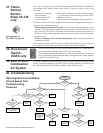
General Troubleshooting
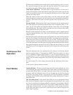
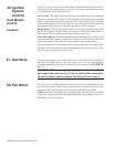
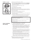
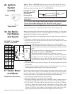
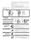
The integrated circuit board monitors the operation of the heater and includes two
LED signal lights that indicate normal operation and various abnormal conditions.
If the heater fails to operate properly, check this signal to determine the cause and/
or to eliminate certain causes. See operating sequence in Paragraph 20.
Do not attempt to repair the DSI integrated control module; the only field replace-
able component is the fuse.
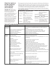
Check the Lights on
the DSI Integrated
Control Module
(Circuit Board)
Control Status - Green LED Codes
Steady ON.. Normal Operation, No call
for heat
Fast Flash ...Normal Operation, Call for
heat
1 Flash........ System Lockout, Failed to
detect or sustain flame
2 Flashes ....Pressure Switch Did Not
Close within 30 Seconds of
Venter Motor
3 Flashes .... High Limit or Flame
Rollout Switch Open
4 Flashes .... Pressure Switch is Closed
Before Venter Motor is
Energized
Steady OFF Blown fuse, No Power, or
Defective Board
Flame Status - Yellow LED Codes
Steady ON.. Flame is sensed
Slow Flash . Weak flame (current below
1.0 microamps ± 50%)
Fast Flash ... Undesired Flame (valve
open and no call for heat)
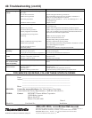
PROBLEM PROBABLE CAUSE REMEDY
1. No power to unit. 1. Turn on power; check supply fuses or main circuit breaker. Turn on
built-in disconnect switch (Model UDAS only); replace switch if not
operating.
2. No 24 volt power to integrated circuit board. 2. Turn up thermostat; check control transformer output.
3. Integrated circuit board fuse blown. 3. Correct cause. Replace fuse (type ATC or ATO, 32VDC, 3A).
4. No power to venter motor. 4. Tighten connections at circuit board and/or motor terminals.
5. Integrated circuit board defective. 5. Replace intergrated circuit board.
6. Defective venter motor. 6. Replace venter motor. See Paragraph 31.
Burner will
1. Manual valve not open. 1. Open manual valve.
not li
g
h
t
2. Air in the gas line. 2. Bleed gas line (initial startup only).
3. Gas pressure too high or too low. 3. Supply pressure should be 5" - 14" w.c. for natural gas or 11" - 14" w.c.
for propane gas.
4. No Spark: 4.
a) Loose wire connections. a) Be certain all wire connections are solid.
b) Transformer failure. b) Be sure 24 volts is available.
c) Incorrect spark gap. c) Maintain spark gap at 1/8".
d) Spark cable shorted to ground. d) Replace worn or grounded spark cable.
e) Spark electrode shorted to ground. e) Replace if ceramic spark electrode is cracked or grounded.
f) Burner not grounded. f) Make certain integrated circuit board is grounded to ignitor.
g) Circuit board not grounded. g) Make certain integrated circuit board is grounded to furnace chassis.
h.) Unit not properly grounded. h.) Make certain unit is properly field grounded to earth ground and
properly phased (L1 to hot lead L2 to neutral).
i) Integrated circuit board fuse blown. i) Correct cause. Replace fuse (type ATC or ATO, 32VDC, 3A).
j.) Faulty intergrated circuit board. j) If 24 volt is available to the integrated circuit board and all other causes
have been eliminated, replace board.
5. Lockout device interrupting control circuit
by above causes.
5. Reset lockout by interrupting control at the thermostat or main power.
6. Interlock door switch open (UDAS only). 6. Close access door or replace switch.
7. Combustion air proving switch 7.
not closing. a) Make sure unit is properly vented.
b) Remove obstructions from vent.
c) Replace faulty tubing to pressure switch.
8. Faulty combustion air proving switch. 8. Replace combustion air proving switch.
9. Main valve not operating. 9.
a) Defective valve. a) If 24 volt is measured at the valve connections and valve remains
closed, replace valve.
b
)
Loose wire connections b
)
Check and ti
g
hten all wirin
g
connections.
Venter motor
will not start
IMPORTANT: When using a
multimeter to troubleshoot the
24 volt circuit, place the
meter’s test leads into the 5 or 9
pin connectors located on the
ignition control. Do not
remove connectors or terminals
from the electrical components.
Doing so can result in misinter-
preted readings due to the
ignition control board’s fault
mode monitoring circuits.


