


Form RZ-NA I-UDA, Mfg #195673 Rev 5, Page 29
27. Burner
Maintenance
This heater is equipped with a TCORE
2
®
burner (patent pending).
Inspect the burner/control compartment annually to determine if cleaning is nec-
essary. If there is an accumulation of dirt, dust, and/or lint, clean the compartment
and follow the instructions below to remove and clean the burner.
CAUTION: Use of eye protection is recommended.
1. Outside the cabinet, shut the gas supply off at the manual valve ahead of the
union.
2. Turn off electric supply.
3. Disconnect the gas supply at the union outside of the cabinet.
4. Remove the access panel.
5. Disconnect the Gas Train and Move Out of the Way - At the gas valve,
mark and disconnect the wires. Carefully remove the burner orifice and
orifice adapter locking nut. Slide the orifice adapter out through the bracket
on the burner pushing the gas train to the right. This will move the gas train
out of the way.
6. Move the Control Assembly - Remove the two screws holding the control
assembly bracket. Being careful not to disconnect any wires, slide the control
assembly to the right.
7. Remove Secondary Air Baffles (Sizes 60-400 only) - Vertical along the right
side of the burner, locate the flat plate(s) identified as the secondary air
baffle(s). The quantity of baffles could be one to four depending on heater
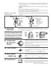
26. Heat
Exchanger
Maintenance
This heater is equipped with a TCORE
2
®
heat exchanger (patent pending).
Remove any external dirt or dust accumulation. Visually check the heat exchanger
for cracks and holes. If a crack or hole is observed, replace the heat exchanger.
NOTE: Inspection of the lower portion of the heat exchanger is done with the
burner removed. See the Burner Service section below for information on inspect-
ing the lower portion of the heat exchanger.
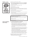
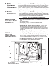
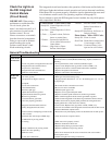
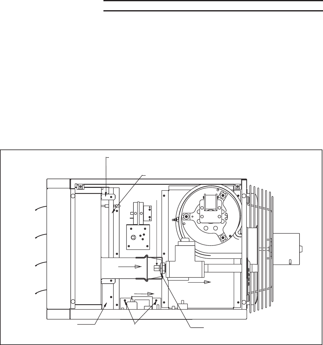
Burner Removal
Instructions (Refer
to FIGURE 17.)
FIGURE 17 - Burner
Removal (UDAP
illustrated; same process
for both UDAP and UDAS)
Venturi Tube
Orifice Adapter Locking Nut
Slide right; rotate
inward; pull out
Gas Valve
Burner
Orifice
Burner Assembly
Secondary Air Baffle
(Qty varies per size.)
Mark locations before removing.
Control Bracket Screws -
Loosen bracket; slide right.
Slide Right
Secondary Air Shield
Burner Body Support (at least two per unit) - Remove screw attaching
to secondary air shield. Support remains attached to burner.
Disconnect gas train at
orifice and outside the
heater; slide to the right.