


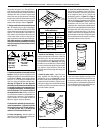
8
NOTE: DIAGRAMS & ILLUSTRATIONS ARE NOT TO SCALE.
5 (127)
8-1/4
(209)
14
(356)
12 (305)
19
(483)
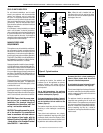
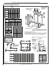
*Shelf Height
(
see table)
Do not insulate the
space between the
appliance and the
area above it.
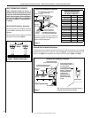
Shelf Above Fireplace With Top Venting
8 (203)
2
(51)
4
(102)
6
(152)
8
(203)
10
(254)
12
(305)
10 (254)
14 (356)
18 (457)
16 (406)
12 (305)
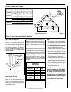
Top of
Appliance
inches (millimeters)
Mantel Depth
Note - Hood shown
as positioned.
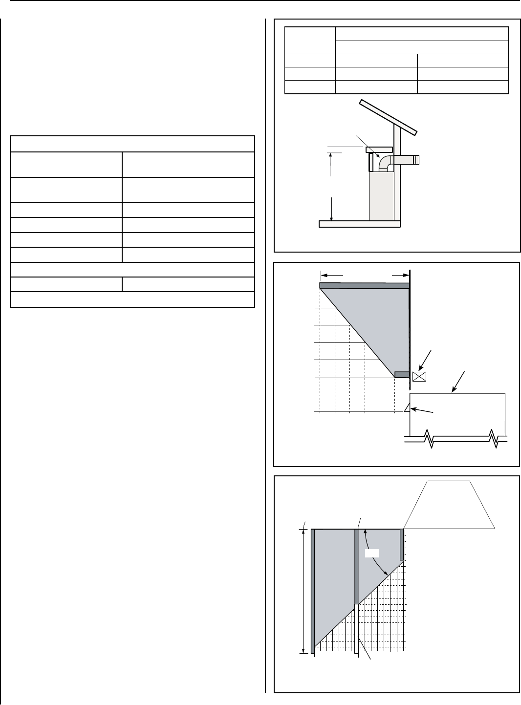
Figure 9 - Minimum Mantel Clearances
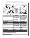
Header
Model No.
Combustible Shelf Height - Inches (millimeters)
Top Vent - with One 90 Degree Elbow
Secure Vent Secure Flex (flex elbow)
SLDVT-30/35 *46-1/2 (1181) *48-1/4 (1226)
SLDVT-40/45 *51-1/2 (1308) *53-1/4 (1349)
Figure 10 - Minimum Distance to Unprotected Side Wall
Top View of
Fireplace
45
o
Protected wall shown in white
Inches (millimeters)
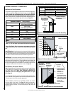
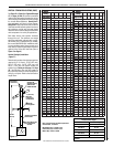
MINIMUM CLEARANCES TO COMBUSTIBLES
Appliance And Vent Clearances
The appliance is approved with zero clearance to combustible materials on
all sides (as detailed in Table 5), with the following exception: When the
unit is installed with one side flush with a wall, the wall on the other
side of the unit must not extend beyond the front edge of the unit. In
addition, when the unit is recessed, the side walls surrounding the unit
must not extend beyond the front edge of the unit (see Figure 3).
*Note: 3 in. (76 mm) above any horizontal/inclined vent component.
**Note: See Page 9, Step 1 for clearance requirements to the nailing
flange located at each side of the unit and any screw heads adjacent
to it.
Hearth Extension - A hearth extension is not required with this appliance.
If a hearth extension is used, do not block the lower control compartment
door. Any hearth extension used is for appearance only and does not have
to conform to standard hearth extension installation requirements.
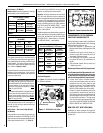
Shelf Height - To provide for the lowest possible shelf surface, the venting
attached to the top vent should be routed in a way to minimize obstructions
to the space above the appliance. Do not insulate the space between the
appliance and the area above it (see Figure 8). The minimum height from
the base of the appliance to the underside of combustible materials used
to construct a utility shelf in this fashion is shown in Figure 8.
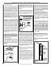
Wall Finishes / Surrounds / Mantels
Note: Combustible wall finish materials and/or surround materials must
not be allowed to en-croach the area defined by the appliance front
face (black sheet metal). Never allow combustible materials to be
positioned in front of or overlapping the appliance face (see Figure
55 on Page 34).
Non-combustible materials, such as surrounds and other appliance trim,
may be installed on the appliance face with these exceptions: they must
not cover any portion of the removable glass panel.
Vertical installation clearances to combustible mantels vary accord-
ing to the depth of the mantel. See Figure 9. Mantels constructed of
non-combustible materials may be installed at any height above the
appliance opening; however, do not allow anything to hang below the
fireplace hood.
* Includes 3” clearance to
combustibles (required above
vent components)
Combustible materials may
project beyond one side
of the fireplace opening
as long as they are kept
within the shaded areas
illustrated here.
Combustible Materials
Allowed In Shaded Area
“Safe Zone”
Combustible Walls
shown in dark gray
At 14" minimum
side wall clearance,
a combustible wall
can project to any
length.
At 8-1/4" side
wall clearance, a
combustible wall
can project 12"
Figure 8 -
Shelf Height Minimum Clearances With Top Venting
MINIMUM CLEARANCES* Inches (millimeters)
Back 1/2 in. (13) or
0 (0) to Spacers Or Dimples
Sides 1/2 in. (13) or
0 (0) to Spacers Or Dimples **
Top 3 (76)
Floor 0 (0)
From Bottom of Unit To Ceiling 64 (1626)
Vent 3 (76)
Top* / 1 (25.4) Sides & Bottom
SERVICE CLEARANCES Feet (meters)
Front 3 feet (0.9 meters)
Table 5
SUPERIOR DIRECT-VENT GAS FIREPLACES • MODELS SLDVT-30/35/40/45 • INSTALLATION INSTRUCTIONS