


Efficiencies (%)
Model
Natural Gas Propane
AFUE EnerGuide (P4) AFUE EnerGuide (P4)
SLDVT-30 57 51 58 54
SLDVT-35 59 59 61 61
SLDVT-40 62 61 64 61
SLDVT-45 64 59 66 61
10
NOTE: DIAGRAMS & ILLUSTRATIONS ARE NOT TO SCALE.
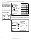
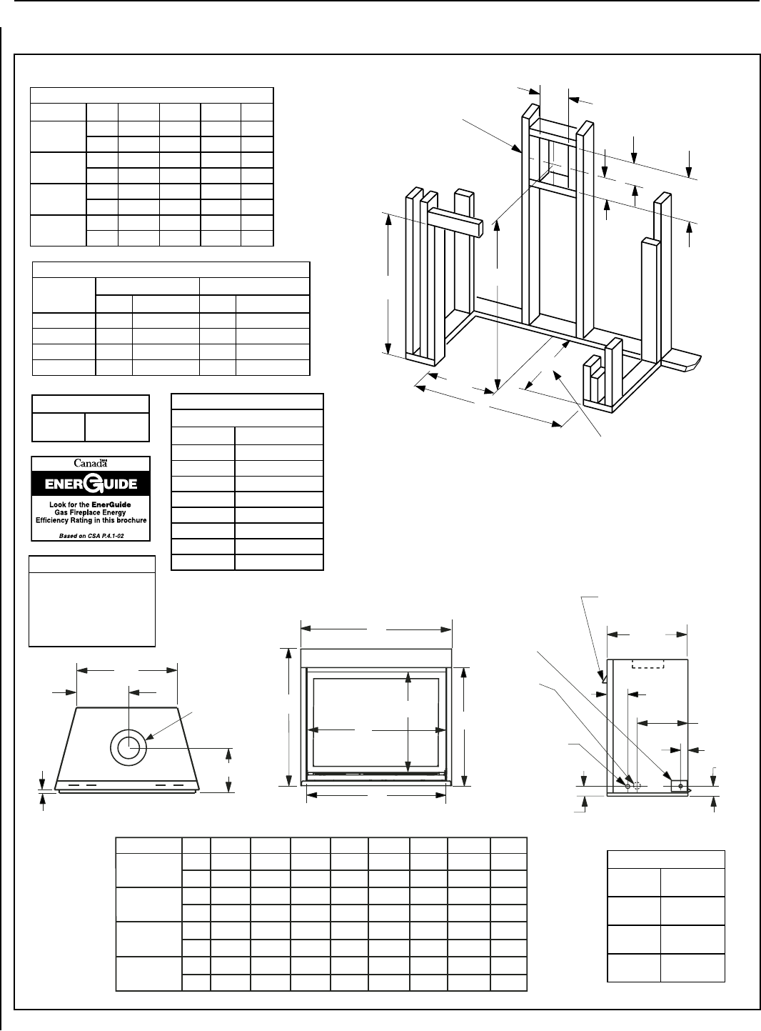
FIREPLACE AND FRAMING SPECIFICATIONS
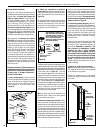
Vent Size
Coaxial DV
Vent Size
4-1/2" Inner
7-1/2" Outer
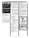
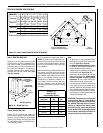
Vertical Venting Through the Ceiling:
Frame ceiling opening - Use a plumb line from the ceiling above the appliance to
locate center of the vertical run. Cut and/or frame an opening, 10-1/2" x 10-1/2" (267
mm x 267 mm) inside dimensions, about this center mark (see Figure 18).
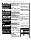
Notes
Diagrams, illustrations and photo-
graphs are not to scale – consult
installation instructions. Product
designs, materials, dimensions,
specifications, colors and prices are
subject to change or discontinuance
without notice.
Input (BTU/HR) - MV & Electronic
Natural & Propane Gas
Models Input Rate (BTU / HR)
SLDVT-30N 13,500
SLDVT-30P 11,500
SLDVT-35N 16,000
SLDVT-35P 15,000
SLDVT-40N 20,000
SLDVT-40P 18,000
SLDVT-45N 23,000
SLDVT-45P 22,000
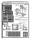
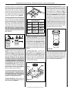
Viewable Glass Size
30" Model
24-1/4" Wide
20-1/4" High
35" Model
29-1/4" Wide
20-1/4" High
40" Model
34-1/4" Wide
25-1/4" High
45" Model
39-1/4" Wide
25-1/4" High
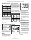
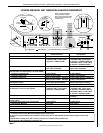
Figure 13
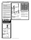
Framing
A
B
C
7
(178)
5-1/8
12-1/8
(308)
10-1/2
(
267
)
D
(130)
A
1/2
Framing Dimensions
Model A B C D
SLDVT-30
in. 30-1/4 35-1/4 39-1/4 16
mm 768 895 997 406
SLDVT-35
in. 35-1/4 35-1/4 39-1/4 16
mm 895 895 997 406
SLDVT-40
in. 40-1/4 40-1/4 44-1/4 16
mm 1022 1022 1124 406
SLDVT-45
in. 45-1/4 40-1/4 44-1/4 16
mm 1149 1022 1124 406
Vent Framing - Top Vent
with One 90° Elbow
Dimension “D” is the required framing depth when the
finish material (drywall) thickness is 1/2 in. (13mm).
Inches (millimeters)
Framing should be
constructed of 2x4 or
larger lumber
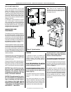
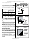
.oNledoM E F G H J K
L M
.ni
mm
SLDVT-35
32-1/4
819
28-1/8
714
23-1/4
590
32
813
35-1/4
895
25
635
12-1/2
317
33
838
.ni
mm
SLDVT-40
37-1/4
946
33-1/8
841
28-1/4
718
37
940
40-1/4
1022
30
762
15
381
38
965
.ni
mm
SLDVT-45
.ni
mm
SLDVT-30
32-1/4
819
37-1/4
946
28-1/8
714
33-1/8
841
23-1/4
590
28-1/4
718
27
686
42
1067
30-1/4
768
45-1/4
1149
20
508
35
889
10
254
17-1/2
445
28
711
43
1092
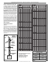
SUPERIOR DIRECT-VENT GAS FIREPLACES • MODELS SLDVT-30/35/40/45 • INSTALLATION INSTRUCTIONS
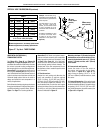
J
Front View
H
G
F
E
M
K
L
Top View
*CONCENTRIC FLUE
FLUE - 4-1/2 (114)
COMBUSTION AIR
- 7-1/2 (190)
9-1/4 (235)
1/2
(13)
16 (406)
1-5/8
(42)
NOTE - Eyebrow
hood shown.
GAS INLET
KNOCKOUT
(Other Side)
Right Side View
5-7/8
(149)
NOTE - It is recommended that the gas be stubbed in from the left
side only.
3 (76)
3 (76)
9-1/2
(241)
ELECTRICAL INLET
KNOCKOUT - 2-3/4 X 2
(70 X 51) COVER PLATE
(With KNOCKOUT -
Right Side Only)
OPTIONAL
ELECTRICAL
INLET KNOCKOUT,
REQUIRING A FIELD
PROVIDED
JUNCTION BOX
(Either Side)