


33
NOTE: DIAGRAMS & ILLUSTRATIONS ARE NOT TO SCALE.
WARNINGS
• Air shutter adjustment should only be performed
by a qualified professional service technician.
• Ensure front glass panel are in place and sealed
during adjustment.
CAUTIONS
• Soot will be produced if the air shutter is closed
too much. Any damage due to sooting resulting
from improperly setting the air shutter is not
covered under the warranty.
• The air shutter door and nearby appliance surfaces
are hot. Exercise caution to avoid injury while
adjusting flame appearance.
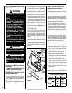
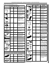
Main Burner Factory Air Shutter
Opening Setting - Inches (millimeter)
Model Nat.Gas Propane Gas
SLDVT-30/35 1/32 (0.795) 3/16" (4.763)
SLDVT-40/45 1/32 (0.795) 3/16" (4.763)
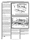
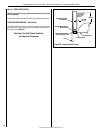
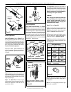
Adjustment
Rod Up
(Fully Open
Position)
Air Shutter
Adjustment Rod Down min.
air opening position)
Burner
Tube
Adjustment Set-Screw
Figure 54 - Burner Air Shutter Adjustment
Ref. Air shutter Patent:
U.S. Pat. 5,553,603
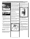
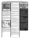
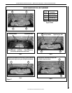
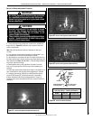
Figure 51 - Burner Flame Appearance Model SLDVT-30 and 35
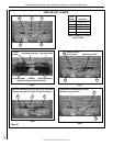
Figure 52 - Burner Flame Appearance Model SLDVT-40
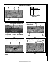
Figure 53 - Burner Flame Appearance Model SLDVT-45
1. Locate adjustment rod and adjust air shutter to the standard set-
ting as shown in Figure 54 (adjustment rod is located in the lower
control compartment).
Note: Move the adjustment rod down to decrease air and up to
increase.
2. Light appliance (follow lighting procedure on lighting label in con-
trol compartment or see the Care and Operation manual).
3. Allow the burner to operate for at least 15 minutes while observing
the flame continuously to ensure that the proper flame appearance has
been achieved (see Figures51, 52 or 53 ). If the following conditions
are present, adjust accordingly.
• If ame appears weak or sooty, adjust the air shutter, incremen-
tally, to a more open position until the proper flame appearance is
achieved.
• If ame stays lowered blue, adjust the air shutter, incrementally, to a
more closed position until the proper flame appearance is achieved.
4. Leave the control knob (off/pilot/on) in the ON position and the
burner OFF/ON switch OFF (and remote switches, if applicable).
5. When satised that the burner ame appearance is normal, re-
install the lower control compartment door then proceed to finish the
installation.
Burner Air Shutter Adjustment Procedure
SUPERIOR DIRECT-VENT GAS FIREPLACES • MODELS SLDVT-30/35/40/45 • INSTALLATION INSTRUCTIONS