


11
NOTE: DIAGRAMS & ILLUSTRATIONS ARE NOT TO SCALE.
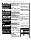
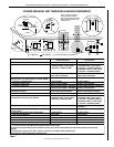
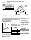
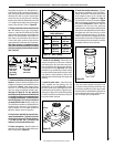
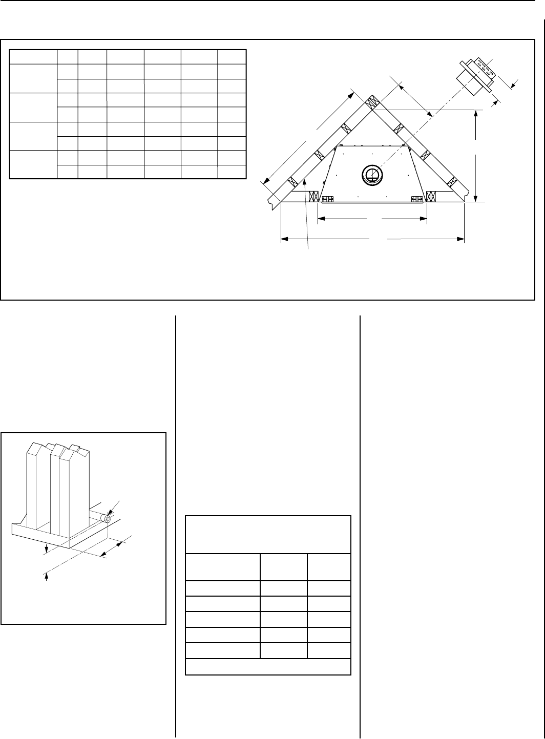
FIREPLACE FRAMING SPECIFICATIONS
Figure 14 - Corner Framing with Horizontal Termination
Inches
(millimeters)
C
Back wall of chase/enclosure
(including any finishing materials)
D
E
A
B
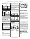
7 (178)
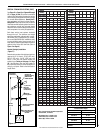
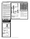
Schedule 40
Black Iron Pipe
Inside Diameter (Inches)
Schedule 40 Pipe
Length (feet)
Natural
Gas
Propane
Gas
0-10 1/2 3/8
10-40 1/2 1/2
40-100 1/2 1/2
100-150 3/4 1/2
150-200 3/4 1/2
Table 6
Notes:
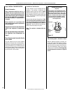
• All appliances are factory-equipped with a
flexible gas line connector and 1/2 inch shutoff
valve (see Figure 40 on Pagec 26).
• See Massachusetts Requirements on Page 4
for additional requirements for installations in
the state of Massachusetts in the USA.
• The gas supply line should Not be connected
to the appliance until Step 6 (Page 26).
• A pipe joint compound rated for gas should be
used on the threaded joints. Ensure propane
resistant compounds are used in propane
applications. Be very careful that the pipe
compound does not get inside the pipe.
• It is recommended to install a sediment trap
in the supply line as close as possible to the
appliance. Appliances using Propane should
have a sediment trap at the base of the tank.
• Check with local building ofcial for local code
requirements (i.e. are below grade penetrations
of the gas line allowed?, etc).
IMPORTANT: If propane is used, be aware that
if tank size is too small (i.e. under 100-lbs, if
this is the only gas appliance in the dwelling.
Ref. NPFA 58), there may be loss of pressure,
resulting in insufficient fuel delivery (which
can result in sooting, severe delayed ignition
or other malfunctions). Any damage resulting
from an improper installation, such as this, is
not covered under the limited warranty.
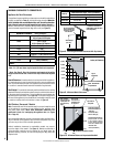
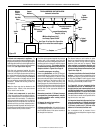
Proper Sizing of Gas Line
Properly size and route the gas supply line
from the supply regulator to the area where the
appliance is to be installed per requirements
outlined in the National Fuel Gas Code, NFPA
54 - latest edition (USA) or CAN/CSA-B149.1
- latest edition (Canada).
Also see Figure 13.
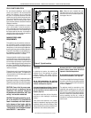
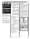
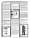
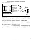
Figure 15 - Route Gas Line
3"
(76 mm)
Left Side Front
Corner of Fireplace
Framing
6-1/2"
(152 mm)
Pipe Coupling
(Recommended)
Step 2. ROUTING GAS LINE
Route a 1/2" (13 mm) gas line to the left side
of the appliance as shown in Figure 15. Gas
lines must be routed, constructed and made
of materials that are in strict accordance with
local codes and regulations. All appliances
are factory-equipped with a flexible gas line
connector and 1/2 inch shutoff valve. (See
Step 6 on Page 26).
Never use galvanized or plastic pipe. Refer to
Table 6 for proper sizing of the gas supply line,
if black iron pipe is being used. Gas lines must
be routed, constructed and made of materials
that are in strict accordance with local codes
and regulations.
We recommend that a qualied individual such
as a plumber or gas fitter be hired to correctly
size and route the gas supply line to the appli-
ance. Installing a gas supply line from the fuel
supply to the appliance involves numerous
considerations of materials, protection, siz-
ing, locations, controls, pressure, sediment,
and more. Certainly no one unfamiliar and
unqualied should attempt sizing or installing
gas piping.
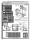
.oNledoM A B D E
in.
mm
SLDVT-30
SLDVT-40
SLDVT-45
SLDVT-35
in.
mm
35 1/4
57 1/2
40 5/8
28 3/4
in.
895
1461
1032
730
mm
40 1/4
1022
61 13/16
1554
43 11/32
1101
30 11/16
779
in.
mm
C
30 1/4
768
53 3/16
1350
37 29/32
963
26 13/16
681
45 1/4
1149
66 1/8
1680
46 1/16
1170
32 5/8
829
12 1/4
311
13 3/4
349
15 1/8
384
16 1/2
419
SUPERIOR DIRECT-VENT GAS FIREPLACES • MODELS SLDVT-30/35/40/45 • INSTALLATION INSTRUCTIONS