


8
NOTE: DIAGRAMS & ILLUSTRATIONS NOT TO SCALE.
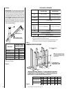
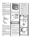
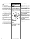
Fireplace may be anchored to floor. Bend down
four (4) anchor tabs located at the base of the
fireplace and secure to the floor by nailing with
8d nails
(Figure 10 ).
2. Measure the square footage of the floor
space to be occupied by the system, surrounds
and hearth extensions.
3. Note the floor construction, i.e. 2 x 6’s, 2 x
8’s or 2 x 10’s, single or double joists, type and
thickness of floor boards.
4. Use this information and consult your local
building code to determine if you need addi-
tional support.
If you plan to raise the fireplace and hearth
extension, build the platform assembly then
position fireplace and hearth extension on top.
Secure the platform to the floor to prevent
possible shifting.
INSTALLING THE FIREPLACE
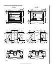
Step 1. Construct the Appliance Framing -
Frame appliance enclosure as illustrated in
Figures 5 through 8 on page 6 and 7
.
(Note: Appliance may be positioned first and
then the framing constructed around it.)
If the appliance is to be elevated above floor level,
a solid continuous platform must be constructed.
IMPORTANT: UNDER NO CIRCUMSTANCES
CAN THE FIREPLACE TOP SPACERS
(FIGURE
2 OR 3 )
BE REMOVED OR MODIFIED, NOR
MAY YOU NOTCH THE HEADER TO FIT
AROUND OR BE INSTALLED LOWER THAN
THE SPACERS. THE HEADER MAY BE IN DI-
RECT CONTACT WITH THE TOP SPACERS
BUT MAY NOT BE SUPPORTED BY THEM.
Consult all local codes.
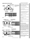
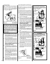
Step 2. Route Gas Supply Line - Route gas
line
(Figure 5 )
using techniques and materials
prescribed by local and/or national codes. It is
recommended that a gas line of ¹⁄₂" or greater
diameter be used to allow full gas volume to
the fireplace. Undue pressure loss will occur if
the pipe is too small.
The gas line should extend a total of 2 in.
(51 mm) maximum into the appliance con-
trol compartment.
When rigid pipe is used, an ANSI approved
manual shut-off valve and union must be in-
stalled upstream of the fireplace.
Ensure that a sediment trap is installed in the
existing gas line, if not, install a sediment trap
upstream to prevent moisture and contaminants
from passing through trap to the appliance con-
trols and burners. Failure to do so could prevent
the appliance from operating reliably.
An external regulator must be used on all pro-
pane (L.P.G.) heaters to reduce the supply tank
pressure to 13" w.c. (maximum). Any copper
tubing used to supply propane (L.P.G.) from
the tank must be internally tinned.
IMPORTANT: HOLD GAS VALVE SECURELY
TO PREVENT MOVEMENT WHEN CONNECT-
ING TO INLET GAS LINE
WARNING: CONNECTING DIRECTLY TO
AN UNREGULATED PROPANE (L.P.G.)
TANK MAY CAUSE AN EXPLOSION.
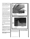
Step 3. Position the Appliance - Slide the
fireplace into prepared framing.
(Note: Appliance may be positioned first and
then the framing constructed around it.)
Fireplace should be secured to side framing
members using the full length ¹⁄₂ inch nailing
flanges that are integral to the appliance at
each side. Use 8d nails
(Figure 9 )
.
Note: The nailing tabs and the area directly
behind the nailing tabs are exempt from the
clearances described on the fireplace clear-
ance label.
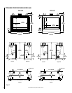
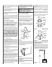
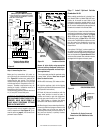
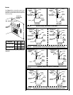
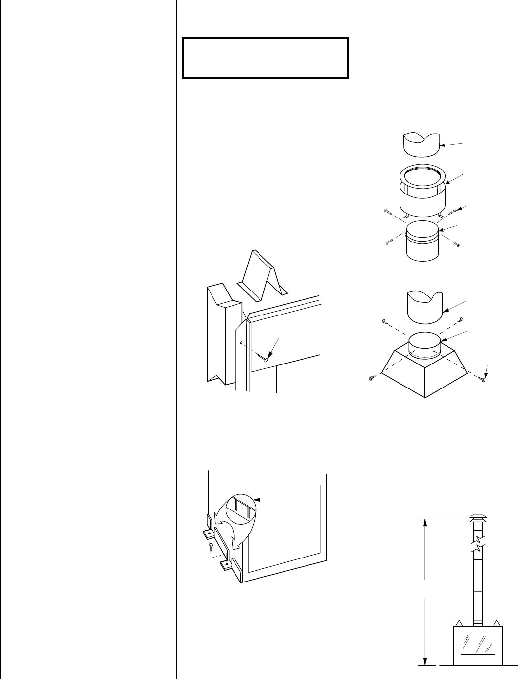
See
Figure 11
for 5500 series units and
Figure 12
for 6500 series. Then install the
remainder of the Type B vent to the outside.
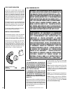
Minimum overall height of the vent system and
appliance must be 12' (3.7 m).
See Figure 13.
Maximum overall height of the vent system and
appliance should not exceed 40 feet (12.19 m).
Install the B-vent system in accordance with
the vent manufacturer's instructions.
Figure 13
CAUTION: THIS APPLIANCE CANNOT BE
VENTED HORIZONTALLY.
Note: Refer to the vent manufacturers installa-
tion instructions for variations of venting tech-
niques. If common venting of several units is
contemplated, it should be discussed with an
architect and the local Building Department.
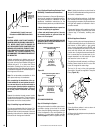
5500 Series Models
Figure 12
6500 Series Models
Figure 11
8d Nail
Anchor
Ta b
Figure 9
Figure 10
5 in.
Type B-Vent
Flue Collar
Assembly
Securing
Screws
Flue Outlet
Collar
Type B Vent
Flue Outlet
Collar
Securing
Screws
12 ft.
Minimum
Step 4. Install the Vent System & Exterior
Termination -
Connect a 5 in. (127 mm) Type B vent system to
the appliance flue collar with four, No. 8 or larger,
sheet metal screws.