


2
NOTE: DIAGRAMS & ILLUSTRATIONS NOT TO SCALE.
TABLE OF CONTENTS
Packaging ........................................ page 2
Introduction ..................................... page 2
General Information ......................... page 2
Location .......................................... page 3
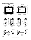
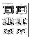
Appliance Specifications - 5500 ...... page 4
Appliance Specifications - 6500 ...... page 5
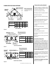
Venting ............................................ page 6
Clearances ....................................... page 6
Framing Specifications .................... page 6
Typical Installation Sequence .......... page 7
Pre-Installation Notes ...................... page 7
Installation ....................................... page 8
Field Wiring ..................................... page 9
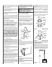
Connecting Gas Line ........................ page 11
Outside Air Kit Installation ............... page 11
Log and Rockwool Installation ........ page 12
Appliance Operation ........................ page 12
Millivolt Appliance Checkout ............ page 12
Electronic Appliance Checkout......... page 13
Safety Limit Switch Operation ......... page 13
Adjustments .................................... page 14
Finishing Requirements ................... page 14
Cold Climate Insulation .................... page 16
Installation Accessories ................... page 16
Gas Conversion Kits .................. page 16
GENERAL INFORMATION
Note: Installation and repair should be per-
formed by a qualified service person. The appli-
ance should be inspected annually by a quali-
fied professional service technician. More fre-
quent inspections and cleanings may be re-
quired due to excessive lint from carpeting,
bedding material, etc. It is imperative that the
control compartment, burners and circulating
air passage ways of the appliance be kept clean.
S'assurer que le brùleur et le compartiment des
commandes sont propres. Voir les instruc-
tions d'installation et d'utilisation qui
accompagnent l'apareil.
This installation manual will help you obtain a
safe, efficient, dependable installation for your
appliance and vent system.Please read and
understand these instructions before begin-
ning your installation.
Provide adequate clearances around air open-
ings and adequate accessibility clearance for
service and proper operation. Never obstruct
the front openings of the appliance.
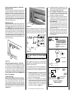
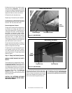
PACKAGING
The assembled vented gas fireplace is pack-
aged with:
1 - one cartoned log set located in firebox area.
2 - one bag of glowing embers (rockwool)
located in the bottom compartment.
3 - one envelope containing the literature
package which consists of the homeowner's
manual, installation instructions, and war-
ranty; envelope is located in the control area.
4 - wall switch for burner operation taped to
top of unit.
WARNING: THESE FIREPLACES ARE
VENTED DECORATIVE GAS APPLIANCES.
DO NOT BURN WOOD OR OTHER MATE-
RIAL IN THESE APPLIANCES.
INTRODUCTION
The GHC-5500/6500N, P models are circulat-
ing system appliances; the GRD-5500/6500N,
P models are radiant heat system appliances;
both types utilize a millivolt gas control valve
and a piezo ignition system. There is no need
for an external power source to operate these
systems. They are designed to operate on
either natural or propane gas.
WARNING: IMPROPER INSTALLATION,
ADJUSTMENT, ALTERATION, SERVICE
OR MAINTENANCE CAN CAUSE INJURY
OR PROPERTY DAMAGE. REFER TO THIS
MANUAL. FOR ASSISTANCE OR ADDI-
TIONAL INFORMATION CONSULT A
QUALIFIED INSTALLER, SERVICE
AGENCY OR THE GAS SUPPLIER.
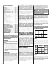
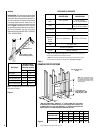
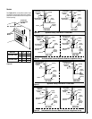
Table 1
shows the units' factory-installed
gas orifice size for installations at elevations
of 0-2000 feet (0-610 meters).
Table 1
Table 2
shows the units' gas orifice size for
installations at elevations greater than 2000 ft.
(0-610 m.). These orifices must be ordered
separately using the kit numbers listed in table 2.
Table 2
These appliances are designed to operate on
natural or propane gas only. The use of
other fuels or combination of fuels will de-
grade the performance of this system and
may be dangerous.
For elevations of 0-2000 ft. (0-610 m.) the
GHC/GRD-5500 input is 24,000 BTU/HR for
both natural and propane gases, the GHC/
GRD-6500 input is 27,000 BTU/HR for both
natural and propane gases.
Nominal operating pressures for the manifold
side of the gas control system are; 3.5 inches
water column (6.54 MmHg) for natural gas
models and 10 inches water column (18.69
MmHg) for propane gas models.
The GHC-5500NE-2, PE-2 and GHC-6500EN,
EP models are circulating system appliances;
the GRD-5500NE-2, PE-2 and GRD-6500EN,
EP models are radiant heat system appliances;
both utilize an electronic gas control valve
along with an intermittent ignition system.
These systems require an external power source
in order to operate. They are designed to oper-
ate on either natural or propane gas.
These appliances comply with National Safety
Standards and are tested and listed by Warnock
Hersey (Report No. J20046562 - for 5500
series; J20046564 - for 6500 series models)
to ANSI Z21.50 - 2000 (in Canada, CSA 2.22 -
2000), and CAN/CGA-2.17-M91 in both USA
and Canada, as vented gas fireplaces.
Installation must conform to local codes. In
the absence of local codes, installation must
comply with the current National Fuel Gas
Code, ANSI Z223.1 (NFPA 54). (In Canada, the
current CAN/CGA B149 installation code.) Elec-
trical wiring must comply with local codes. In
the absence of local codes, installation must
be in accordance with the National Electrical
Code, NFPA 70 - (latest edition). (In Canada,
the current CSA C22.1 Canadian Electric Code.)
DO NOT ATTEMPT TO ALTER OR MODIFY
THE CONSTRUCTION OF THE APPLIANCE OR
ITS COMPONENTS. ANY MODIFICATION OR
ALTERATION MAY VOID THE WARRANTY,
CERTIFICATION AND LISTINGS OF THIS UNIT.
CHG
DRG
seireS
ezisecifirO
noitavelE
teeF
)sretem(
.taN.porP
0055 34#45#
0002-0
)016-0(
0056 14#35#
CHG
DRG
seireS
ezisecifirO
)rebmuNtiK(
noitavelE
teeF
)sretem(
.taN.porP
0055
44#
)116040(
55#
)216040(
retaerg
naht
0002
)016(
0056
34#
)619150(
55#
)719150(