


11
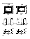
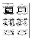
NOTE: DIAGRAMS & ILLUSTRATIONS NOT TO SCALE.
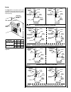
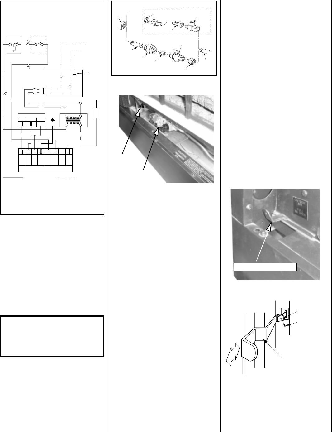
Figure 24
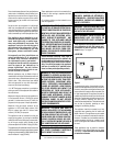
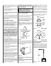
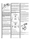
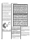
Step 6. Connecting Gas Line –
Make gas line connections. All codes re-
quire a shut-off valve mounted in the supply
line.
Figure 23
illustrates two methods for
connecting the gas supply. The flex-line
method utilizing the gas flex line provided
with the appliance is acceptable in the U.S.,
however, Canadian requirements vary de-
pending on locality. Installation must be in
compliance with local codes.
The millivolt and electronic control valve have
³⁄₈" (10 mm) NPT thread inlet ports.
Secure all joints tightly using appropriate
tools and sealing compounds (ensure pro-
pane resistant compounds are used in pro-
pane applications).
Turn on gas supply and test for gas leaks using
a soapy water solution. Never use an open
flame to check for leaks.
A. Mix a 50% dish soap, 50% water solution.
B. Light the appliance (refer to the lighting
instructions provided in the Homeowner's Care
and Operation Instructions).
C. Brush all joints and connections with the
soapy water solution to check for leaks. If
bubbles are formed, or gas odor is detected,
turn the gas control knob to the “OFF” posi-
tion. Either tighten or refasten the leaking
connection and retest as described above.
D. When the gas lines are tested and leak free,
observe the individual tongues of flame on the
burner. Make sure all ports are open and
producing flame evenly across the burner. If
any ports are blocked, or partially blocked,
clean out the ports.
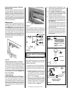
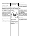
The gas control valve is located in the lower
control compartment.
See Figure 24.
To ac-
cess the valve see
page 9,
the Control Com-
partment Access Section.
Figure 23
WARNING: TO PREVENT DAMAGE TO
THE VALVE AND OTHER ATTACHED COM-
PONENTS, HOLD VALVE FIRMLY IN
PLACE WHILE TIGHTENING FITTINGS
USED IN THE NEXT STEP.
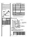
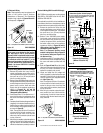
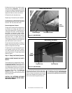
Figure 25
Figure 26
Combustion Air Control Lever and
Extension on GHC-6500 Series Units
Location of Controls
GHC/GHR-5500 SERIES
Step 7. Install Optional Outside
Combustion Air Kit
When outside combustion air is desired, Len-
nox' Model FOAK-4 or Model FOAK-4LD com-
bustion air kit should be used. Refer to the
installation instructions packed with the air kit
for specific installation information. The outside
air kit must be installed before the appliance is
framed and enclosed in the finished walls.
The control lever, located on the left side of the
appliance front opening, controls the entrance
of combustion air from the outside. See
Figure
25
for 5500 series units,
Figure 26
for GHC-
6500 series units or
Figure 27
for GRD-6500
series units. The 6500 series units have a cover
over the control lever fastened by one screw.
Remove the screw and then the cover and
discard them.
If an optional “All-Glass” enclosure panel is to
be installed on the 6500 Series appliances, an
extension bar must be attached to the actuator
lever as illustrated in
Figures 26 and 27
. Both
versions of the actuator lever extension bar are
packaged with the glass enclosure panel.
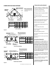
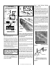
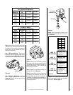
Figure 22
Electronic System Wiring
(Without Forced Air Kit)
1. If any of the original wire as supplied must be replaced,
1. it must be replaced with Type AWM 105°C – 18 GA. wire.
2. 120V, 60Hz – Less than 3 amps.
LIMIT SW
ON/OFF SW
120 VAC. BK
GND
NEU. W
Ignitor
Junction Box
Transf.
120 V.
W
BK
Gas Valve
M
C
BK
24 V
MV
24V
GND
PV
Ignition Control
Factory Wired
Field Wired
P
PV/MV
G
BL
BK
W
GHC/GRD-5500/6500
(Honeywell Ignition Module Equipped)
24V
Low Voltage
BK
GND
(Burner)
24V
TH-W
(OPT.)
SPARK
W
BL
R
Green
Ground
Screw
BK
R
Gas Stub
³₈" Flare x ¹₂" NPT
Shut-Off Valve
³₈" Flex Tubing
³₈" NPT x ³₈"
Flare Fitting
³₈" Nipple
³₈"
Union
³₈" Close Nipple
³₈" Shut-Off Valve
³₈
" x
¹₂
"
Reducer
Gas
Valve
Gas Flex Line Connector
Extension Bar
Actuator Lever
Phillips Pan
Head Screw
#6-32 x ⁷⁄₃₂"
(6 mm)
O
C
Piezo Ignitor
Millivolt
Gas Valve
Combustion Air Control Lever