


12
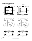
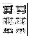
NOTE: DIAGRAMS & ILLUSTRATIONS NOT TO SCALE.
CAUTION: NEVER LOCATE INLET WHERE IT
CAN BE BLOCKED BY SHRUBS, SNOW DRIFTS,
ETC. NEVER LOCATE INLET IN GARAGE OR
ANY AREA WHERE THERE IS ANOTHER FUEL
BURNING APPLIANCE OR PRODUCTS EMIT-
TING COMBUSTIBLE GASES SUCH AS PAINT,
GASOLINE, ETC. IN COLD CLIMATES, IT IS
RECOMMENDED THE COMBUSTION AIR DUCT
BE INSULATED.
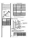
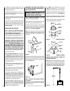
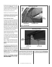
Outside combustion air ducting may be run
upwards or vertically through framing and ceil-
ing joists, with the hood installed through an
outside wall and 3' (1 m) below the B-Vent
termination. Ducting may also be run down-
ward through floor joists and under the home to
a ventilated crawlspace not considered part of
the living area of the home.
Note: Do not terminate combustion air kit in
attic space under any circumstances.
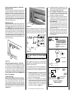
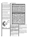
After completing the installation of the op-
tional combustion air vent system the actua-
tor arm must be put in service and tested to
ensure proper operation before completing
any enclosure around the firebox. Failure to
do so may result in extensive and costly
rework.
Operate the actuator through several cycles
including the closed position. Ensuring proper
operation and freedom of movement. Return
the actuator arm to the closed position.
Step 8. Installing Logs and Rockwool –
The logs are packaged within the firebox. The
bag of rockwool is in the lower control com-
partment. Refer to the Homeowner's Care and
Operating Instructions for detailed placement
instructions for the logs and rockwool.
Step 9. Optional Glass Doors/Enclosure Panel
Availablity, Precautions and Instructions –
See the Homeowner's Care and Operating In-
structions for a selection of glass doors/enclo-
sure panels available for installation in these
appliances. Installation Instructions for the
doors/enclosure panels are provided with them.
• Never clean glass when doors or panel are
hot due to operating the appliance.
• Glass and metal frames get hot. Use only
the wooden handles to open and close the
doors or to lift out panel.
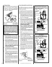
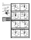
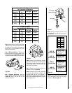
Figure 28
Figure 29
CAUTION: THE APPLIANCE SHOULD ONLY BE
OPERATED WITH THE GLASS DOORS FULLY
OPEN OR FULLY CLOSED.
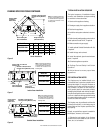
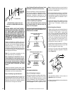
Combustion Air Control Lever and
Extension on GRD-6500 Series Units
Figure 27
Note: Lighting instructions are also found on
the pull-out label attached near the gas valve in
the control compartment.
When first lighting the appliance, it will take a
few minutes for the line to purge itself of air.
Once purging is complete, the pilot and burner
will light and operate as indicated in the in-
struction manual.
Subsequent lightings of the appliance will not
require such purging. Inspect the pilot flame
(remove logs, if necessary, handling care-
fully).
Millivolt Appliance Checkout
The gas control system on these appliances is
a millivolt standing pilot type. It consists of a
pilot burner, a piezo ignitor, a gas control
valve, a burner assembly and an ON/OFF wall
switch. A temperature limit switch is wired in
series with the millivolt wall switch and gas
control valve. If a higher than normal tempera-
ture is sensed due to a blocked vent or pro-
longed downdraft, the limit switch will open
and cause the burner to shut off.
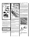
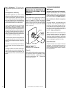
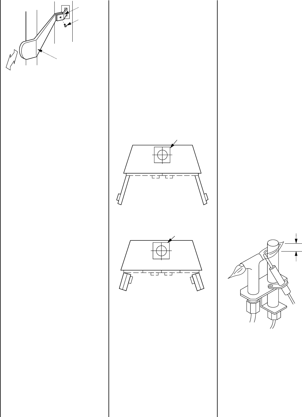
The pilot flame should be steady, not lifting or
floating. Flame should be blue in color with
traces of orange at the outer edge.
The top ³⁄₈" (9 mm) at the pilot generator
(thermopile) should be engulfed in the pilot
flame
(Figure 30 ).
Figure 30
Extension Bar
Actuator
Lever
Phillips Pan
Head Screw
#6-32 x ⁷⁄₃₂"
(6 mm)
O
C
Glass Doors
Fully Open or
Fully Closed
(Twin-Pane Doors)
Rectangular Housing Not Used on
5500 Series Units
Glass Doors
Fully Open or
Fully Closed
(Bi-Fold Doors)
Rectangular Housing Not Used on
5500 Series Units
³⁄₈" (10 mm)
APPLIANCE OPERATION
Step 10. Checking the System –
With gas line installed, run initial system check-
out before closing up the front of the unit.
Follow the pilot lighting instructions provided
in the Homeowner's Care and Operation In-
structions. For piezo ignitor location see
Fig-
ure 24 on page 11
(millivolt appliances only).
If the pilot flame pattern is not as shown in
Figure 30
, adjust it as follows:
1. Remove the pilot adjustment cap located on
the main gas valve.