


7
NOTE: DIAGRAMS & ILLUSTRATIONS NOT TO SCALE.
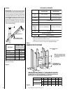
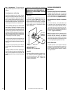
PRE-INSTALLATION NOTES
The fireplace may be installed directly on a
combustible floor or raised on a platform of an
appropriate height. Do not place fireplace on
carpeting, vinyl or other soft floor coverings. It
may, however, be placed on flat wood, ply-
wood, particle board or other hard surfaces,
extending the full depth and width of the appli-
ance. Be sure fireplace rests on a solid continu-
ous floor or platform with appropriate framing
for support and so that no cold air can enter the
room from under the fireplace.
The fireplace may be positioned and then the
framing built around it, or the framing may be
constructed and the fireplace positioned into
the opening.
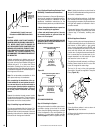
Usually, no special floor support is needed for
the fireplace, however, to be certain:
1. Estimate the total weight of the fireplace
system and surround materials such as brick,
stone, etc., to be installed.
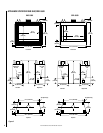
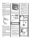
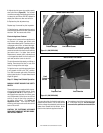
Figure 7
Inside Chase Installation
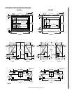
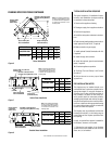
FRAMING SPECIFICATIONS CONTINUED
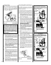
Figure 8
Outside Chase Installation
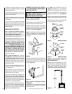
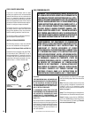
TYPICAL INSTALLATION SEQUENCE
The typical sequence of installation follows,
however, each installation is unique resulting
in variations to those described.
1. Construct the appliance framing.
2. Route gas supply line to appliance location.
3. Position the appliance.
4. Install the vent system and exterior termina-
tion.
5. Field wire and install operating control switch.
Install optional Forced Air Kit, if required
6. Make connection to gas supply.
7. Install optional Outside Combustion Air Kit,
if required.
8. Install the logs and rockwool.
9. Install the optional glass doors/enclosure
panel, if required
10. Checkout appliance operation.
11. Spillage Test and Safety Limit Switch
Operation.
12. Adjust burner to ensure proper flame
appearance.
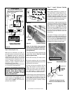
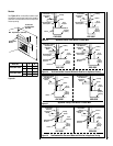
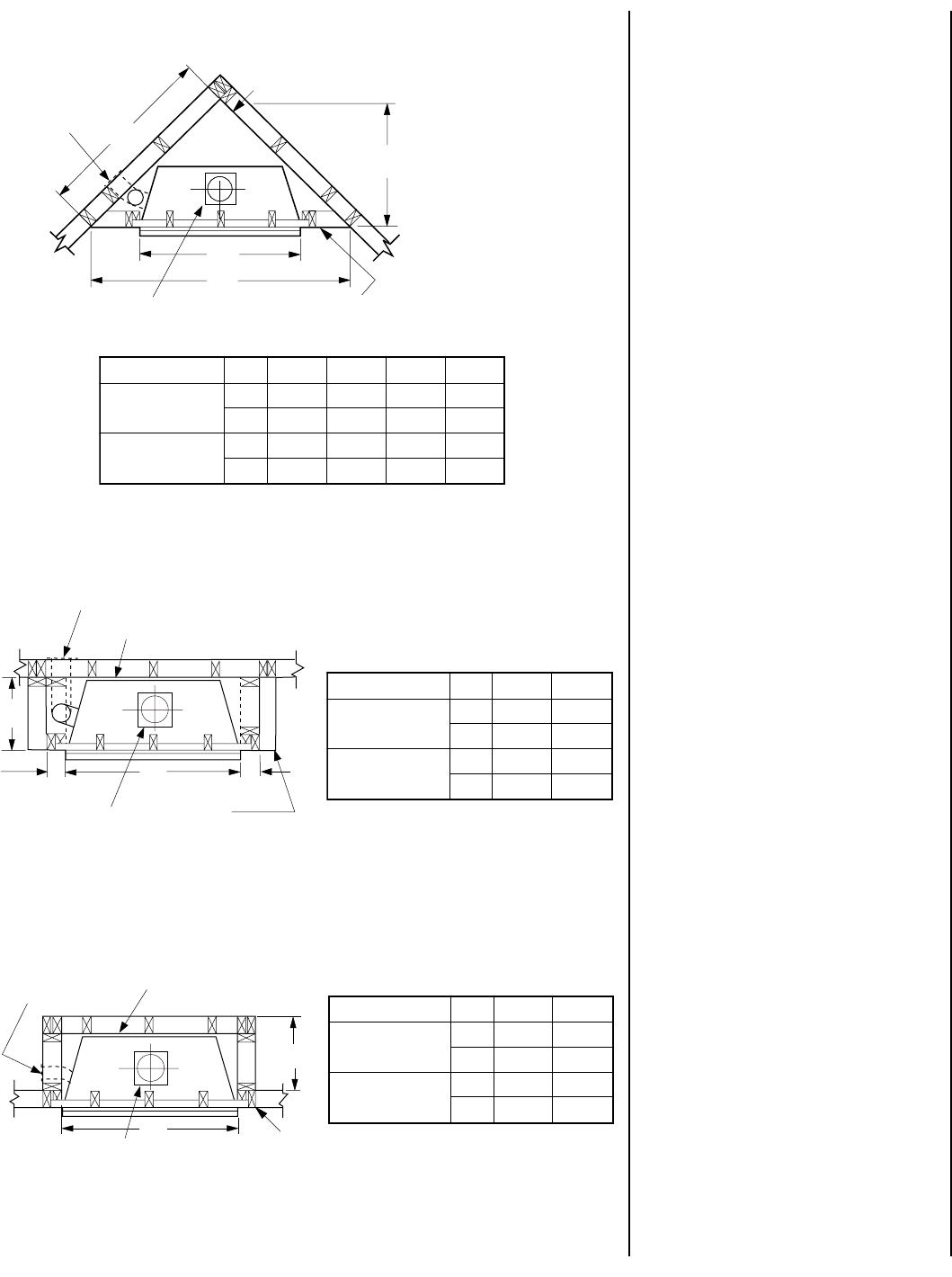
Figure 6
Corner Installation
B
A
C
D
Back Wall of Chase/Enclosure
Including Finishing Materials,
If Any.
Rough Framing Face
(Unfinished Shown)
Note: If the Outside Combustion
Air Kit is to be installed, it must
be installed before the appliance
is framed and enclosed in the
finishing walls.
Optional FOAK-4
or FOAK-4LD
Outside Air Kit
Square Housing Not
Used on 5500 Model
.oNledoMABCD
0055-DRG/CHG
.ni752/163044/392
mm16414195301737
0056-DRG/CHG
.ni564/3044/32/1648/723
mm076153011811538
B
A
Back Wall of Chase/Enclosure
Including Finishing Materials, If Any.
Rough
Framing Face
(Unfinished Shown)
Optional FOAK-4 or FOAK-4LD
Outside Air Kit
4 IN.
(103 MM)
Note: If the Outside Combustion
Air Kit is to be installed, it must
be installed before the appliance
is framed and enclosed in the
finishing walls.
Square Housing Not
Used on 5500 Model
4 IN.
(103 MM)
.oNledoMAB
0055-DRG/CHG
.ni63512/1
mm419493
0056-DRG/CHG
.ni044/381
mm5301754
.oNledoMAB
0055-DRG/CHG
.ni63512/1
mm419493
0056-DRG/CHG
.ni044/381
mm5301754
B
A
Back Wall of Chase/Enclosure
Including Finishing Materials, If Any.
Rough
Framing Face
(Unfinished Shown)
Optional FOAK-4
or FOAK-4LD
Outside Air Kit
Note: If the Outside Combustion
Air Kit is to be installed, it must
be installed before the appliance
is framed and enclosed in the
finishing walls.
Square Housing Not
Used on 5500 Model