


10
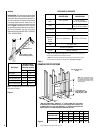
NOTE: DIAGRAMS & ILLUSTRATIONS NOT TO SCALE.
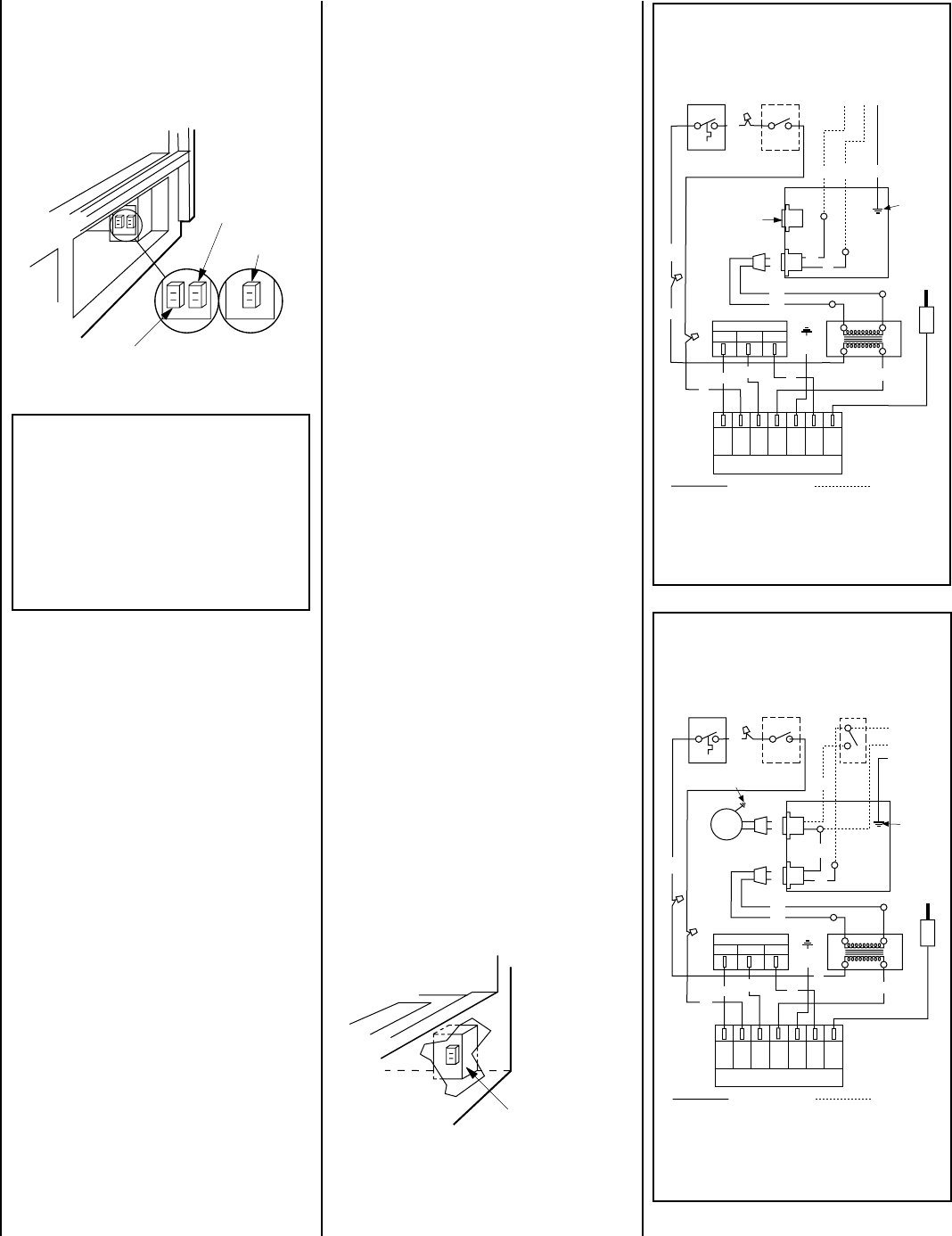
Electronic Wiring (Without Forced Air Kit Usage)
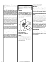
1 - Remove the junction box cover from the
outside right bottom corner of the unit by
removing the hex head screw. The junction
box cover has a ⁷⁄₈ in. (22 mm) knockout
hole for a conduit bushing.
2 - Route a 3 wire 120V 60Hz power supply line
through a wall switch to the junction box and
connect the ground wire to the junction box
ground screw, and the black and white
supply wires to the appliance recptacle as
shown in
Figures 18, 19; and 20
(Robertshaw Ignition Module) or 22
(Honeywell Ignition Module).
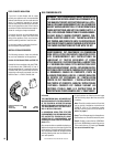
3 - Install the provided “J” box plate on the “J”
box within the control compartment using
the screw and washer provided with the
plate.
4 - Locate and install the low voltage wall switch
(supplied) in the desired location and con-
nect it to the low voltage circuit using the 18
ft of 2 conductor wire supplied with the unit
as shown in
Figure 20.
Note: The supplied 18 feet of 2 conductor
wire has one end of each conductor con-
nected to the gas valve circuit and the
other end of each conductor placed loose
on top of the unit.
5- After wiring is complete, replace the appliance
junction box cover into the side access open-
ing, from which it was removed, and secure
with the hex head screw previously removed.
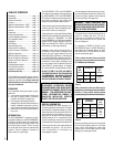
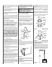
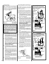
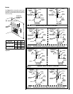
Figure 20
Electronic System Wiring
(Without Forced Air Kit)
Figure 18
Figure 19
GHC-5500/6500
GRD-5500/6500
Electronic Wiring (With Forced Air Kit Usage) –
GHC-5500 series models may use the optional
FAB-1500 or FAB-1600 Forced Air Kit; GHC-
6500 the FAB-1600 Kit.
If an optional forced air kit is to be installed now
or sometime in the future, the appliance must be
connected to the main power supply at this time.
1 - Remove the junction box cover from the
outside right bottom corner of the unit by
removing the hex head screw. The junction
box cover has a ⁷⁄₈ in. (22 mm) knockout
hole for a conduit bushing.
2 - Route a 3 wire 120V 60Hz power supply
line through a wall switch to the junction
box and connect the ground wire to the
junction box ground screw, and the black
and white supply wires to the appliance
recptacle as shown in
Figure 18; and 21
(Robertshaw Ignition Module) or 22
(Honeywell Ignition Module).
Note: If a Honeywell ignition control
module is being used, refer to Figure 22
for the control wiring and Figure 21 for
the blower wiring.
3 - Install the provided “J” box plate on the “J”
box within the control compartment using
the screw and washer provided with the
plate.
4 - Refer to
Figure 18 and 21
and the instal-
lation instructions provided with the forced
air kit(s) for blower connections to the
appliance receptacle and ground.
5 - Locate and install the low voltage wall
switch (supplied) in a desired location and
connect it to the millivolt circuit using the
18 ft of 2 conductor wire supplied with the
unit
(See Figure 21).
Note: The supplied 18 feet of 2 conductor
wire has one end of each conductor con-
nected to the gas valve circuit and the
other end of each conductor placed loose
on top of the unit.
6 - After wiring is complete, replace the appli-
ance junction box cover into the side ac-
cess opening, from which it was removed,
and secure with the hex head screw previ-
ously removed.
IMPORTANT: Ground lead must be connected
to the green screw located on the junction
box. See
Figure 17, 20, 21, or 22
. Failure to
do so will result in a potential safety hazard.
The appliance must be electrically grounded
in accordance with local codes or, in the
absence of local codes, the National Electri-
cal Code, ANSI/NFPA 70-(latest edition). (In
Canada, the current CSA C22-1 Canadian
Electrical Code.)
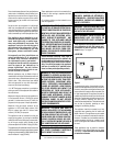
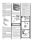
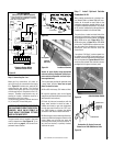
Figure 21
Electronic System Wiring
(With Forced Air Kit)
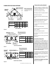
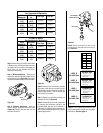
B. Electronic Wiring
Note: These appliances may be equipped with
either of two ignition control modules:
Robertshaw or Honeywell. The Robertshaw
module wiring is shown in Figures 20 and 21;
the Honeywell, in Figure 22.
Transformer
Optional
Blower
Electronic Millivolt
Blower
Note: “J” box plates are not affixed in place at the factory.
Electronic
120V Receptacle
Note: “J” box plate is not affixed in place at the factory.
1. If any of the original wire as supplied must be replaced,
1. it must be replaced with Type AWM 105°C – 18 GA. wire.
2. 120V, 60Hz – Less than 3 amps.
LIMIT SW.
ON/OFF SW
GND
Ignitor
Junction Box
Transf.
120 V.
W
BK
Gas Valve
M
C
BL
BK
24 V
MV
TH
TR
GND
PV
IGN
Ignition Control
Factory Wired
Field Wired
P
PV/MV
GND
W
BL
BK
W
GHC/GRD-5500/6500
Robertshaw Ignition Control Equipped
24V
LOW
VOLTAGE
120 VAC
BK
BK
W
GHC Series Only
Green
Ground
Screw
R
BK
R
1. If any of the original wire as supplied must be replaced,
1. it must be replaced with Type AWM 105°C – 18 GA. wire.
2. 120V, 60Hz – Less than 3 amps.
LIMIT SW
ON/OFF SW
GND
W
Ignitor
Junction Box
Transf.
120 V.
W
BK
Gas Valve
M
C
BL
BK
24 V
MV
TH
TR
GND
PV
IGN
Ignition Control
Factory Wired
Field Wired
P
PV/MV
GND
W
BL
BK
W
GHC-5500/6500
Robertshaw Ignition Control Equipped
24V
LOW
VOLTAGE
120 VAC
BK
BK
Opt
Blower
WALL BLOWER SW
BK
Green
Ground
Screw
Appliance
Ground
Screw
R
BK
R