


8
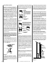
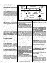
NOTE: DIAGRAMS & ILLUSTRATIONS NOT TO SCALE.
21¹⁄₂
(546)
13
(330)
¹⁄₂
(13)
1⁵⁄₈
(42)
8¹¹⁄₃₂
(212)
3 (76)
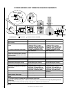
Top View
NOTE - Eyebrow
hood shown as positioned
in louvered front model.
*CONCENTRIC FLUE
FLUE - 4¹⁄₂ (114)
COMBUSTION AIR - 7¹⁄₂ (190)
FRAMING
SPACERS
(Top and Sides
and Rear)
GAS INLET
(Either Side
and bottom)
Front View
3 (76)
(Louvered Front Model Shown)
**Rear vent models only
ELECTRICAL INLET
2³⁄₄ x 2 (70 x 51)
COVER PLATE with
KNOCKOUT)
Right Side View
*DR models have only a rear vent
*DT models have only a top vent
6¹³⁄₁₆
(173)
2³⁄₄
(70)
33¹⁄₈
(841)
30¹⁄₈
(765)
27¹⁄₂
(699)
17
(432)
**19⁵⁄₈
(498)
10³⁄₄
(273)
33¹⁄₈
(841)
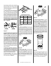
Inches (millimeters)
1 (25)
1
(25)
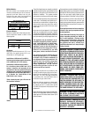
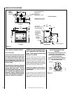
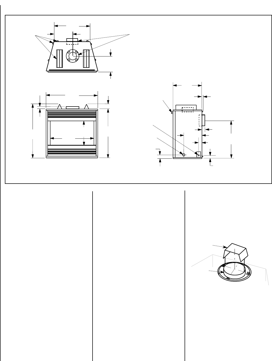
VENT RESTRICTOR INSTALLATION
(TOP VENT)
In all venting applications using the top vent of
the appliance, a vent restrictor may be
needed. Install the vent restrictor in the top
vent of the appliance outlet.
RESTRICTOR
APPLIANCE TOP VENT OUTLET
If needed, install the restrictor orientated as
shown, either from inside or outside the unit,
in the inner fireplace collar.
INNER
FIREPLACE
COLLAR
Figure 11
Figure 12
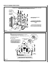
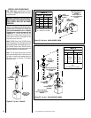
Step 3. INSTALL THE VENT SYSTEM
General Information
These instructions should be used as a guide-
line and do not supersede local codes in any
way. Install vent according to local codes,
these instructions, the current National Fuel
Gas Code (ANSI-Z223.1) in the USA or the
current standards of CAN/CGA-B149.1 and -
B149.2 in Canada.
These fireplaces are designed, tested and
listed for operation and installation with,
and only with, Secure Vent™ (SV 4.5)
Direct Vent System Components, Secure
Flex™ Flexible Vent Components manu-
factured by Security Chimneys Interna-
tional. These approved vent system com-
ponents are labeled for identification.
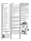
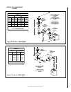
FIREPLACE SPECIFICATIONS
DO NOT use any other manufacturer's
vent components with these appli-
ances. These fireplaces must be vented
directly to the outside.
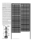
The vent system may not service multiple
appliances, and must never be connected to a
flue serving a solid fuel burning appliance. The
vent pipe is tested to be run inside an enclos-
ing wall (such as a chase). There is no require-
ment for inspection openings in the enclosing
wall at any of the joints in the vent pipe.
Preparing the Appliance Top Vent Outlet in
All Venting Applications Using the Appliance
Top Vent Outlet
A vent restrictor may be needed with this
appliance. Install the vent restrictor (provided)
in the appliance top flue outlet as shown in
Figure 12
. It is held in place by friction, only.