


21
NOTE: DIAGRAMS & ILLUSTRATIONS NOT TO SCALE.
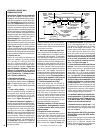
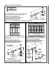
FBK-250 Blower Kit (See
Figure 46
)
An electrical outlet box is provided for the instal-
lation of the FBK-250 forced air blower kit.
Electrical power must be provided to this box to
operate these blowers. Install the blower kit
according to the installation instructions pro-
vided with the kit.
1. Route a 3-wire, 120Vac 60Hz 1ph power line
to the lower right rear corner of the appliance.
2. Remove the outlet box by removing two
screws.
3. Connect the black supply wire to both of the
outlet box' pigtail leads and the white supply
wire to the common terminal of the outlet box
as shown in
Figure 46
.
4. Connect the ground supply wire to the
outlet's green ground screw.
5. Reinstall the outlet box.
6. Insert the kit-provided module plug into the
top outlet.
(The bottom outlet is unused on millivolt
units, while the burner control circuit plugs
into the bottom outlet on electronic units.)
7. Insert the blower plug into the module's
receptacle.
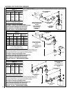
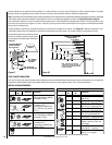
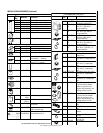
Figure 46
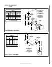
1. If any of the original wire as supplied must be replaced,
1. it must be replaced with Type AWM 105°C – 18 GA. wire.
2. 120V, 60Hz – Less than 3 amps.
BK
Transf.
120 V.
24 V
Factory Wired Field Wired
BL
Electronic Wiring Diagram (Honeywell)
Showing the Blower Wiring for the Optional
FBK-250 Kits
R
WH
BL
OPT
BLOWER
G
W
120
VAC.
BK
W
Gas Valve
B
R
IGNITER
PILOT
ASSEMBLY
BK
G
Outlet Box Green
Ground Screw
Hot side of Outlet
Schematic Representation Only
*ON/OFF Switch (Integral
with Gas Valve)
White Wire
To Opposite
Side
Optional FBK-250
Module
*Leave the ON/OFF switch, which is integral
with the gas valve, in the ON position.
G
OPTIONAL APPLIANCE-MOUNTED ON/OFF SWITCH
OR OPTIONAL WALL SWITCH
OR OPTIONAL THERMOSTAT
OR OPTIONAL REMOTE RECEIVER
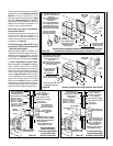
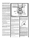
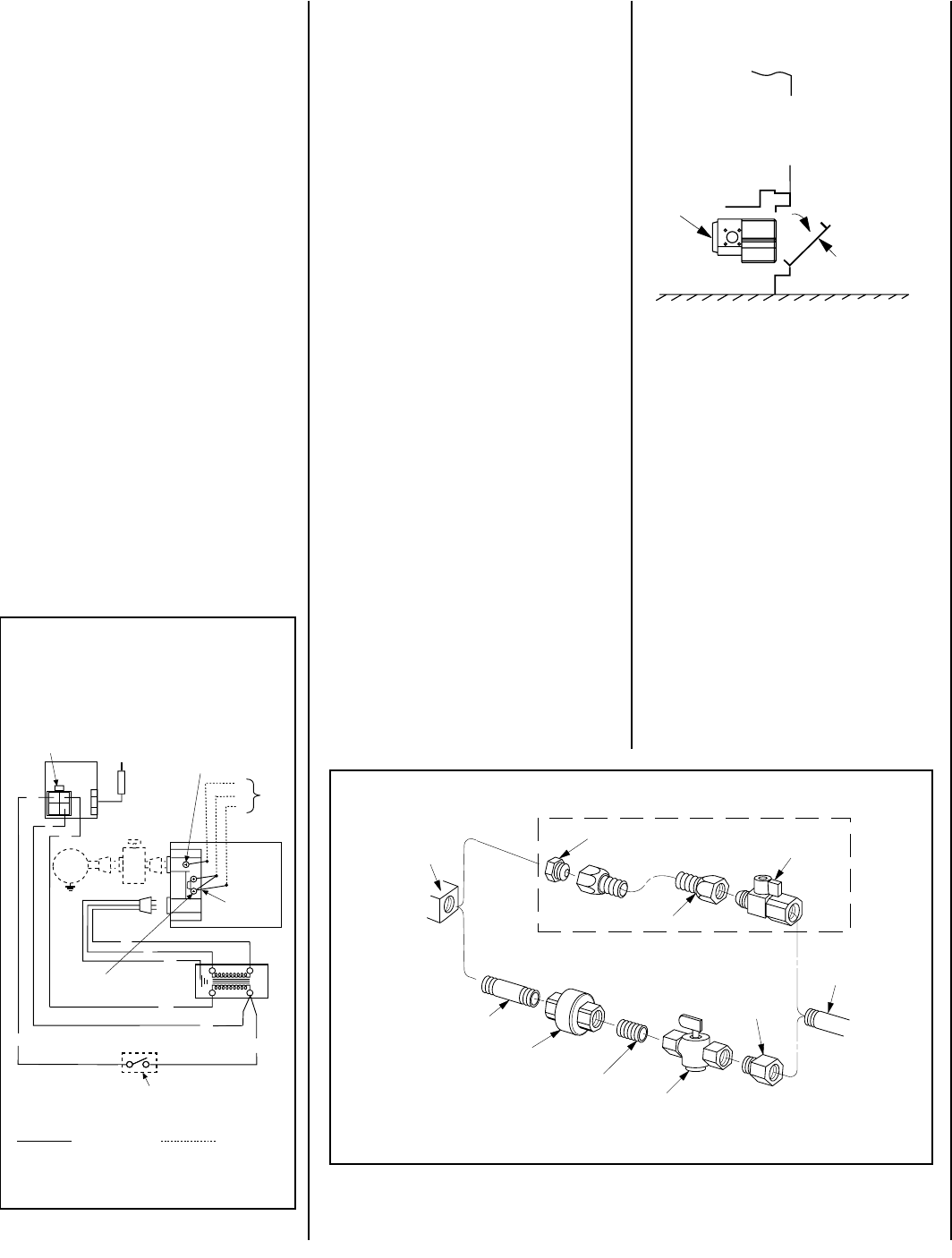
Gas
Stub
¹₂" x ³₈" Flare
Shut-Off Valve
³₈" Flex Tubing
³₈" NPT x ³₈
Flare Fitting
³₈" Nipple
³₈" Union
³₈" Close Nipple
³₈" Shut-Off Valve
¹₂ x ³₈ "
Reducer
Gas
Valve
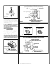
Optional Gas Flex Line Connector
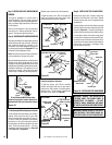
Figure 47 -
GAS CONNECTION
Step 6. CONNECTING GAS LINE
Make gas line connections. All codes re-
quire a shut-off valve mounted in the supply
line.
Figure 47
illustrates two methods for
connecting the gas supply. The flex-line
method is acceptable in the U.S., however,
Canadian requirements vary depending on
locality. Installation must be in compliance
with local codes.
These appliances can be equipped with a gas
flex line for use (where permitted) in connect-
ing the unit to the gas line. The gas flex line
(not provided) is to aid in attaching the direct
vent appliance to the gas supply. The gas flex
line can only be used where local codes per-
mit. See
Figure 47
for flex line description.
The flex line is rated for both natural and
propane gas. The optional gas flex line is
equipped with a manual shut off valve.
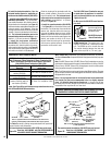
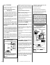
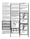
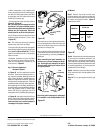
Open the control compartment access panel
(Figure 48)
by actuating the spring-loaded
magnetic catches securing the panel, gently
depressing the outer top corners of the panel
until the catches "pop" the panel free, allowing
it to swing out and down to open.
The millivolt control valve has a ³⁄₈"
(10 mm) NPT thread inlet port.
Secure all joints tightly using appropriate
tools and sealing compounds (ensure pro-
pane resistant compounds are used in pro-
pane applications).
Turn on gas supply and test for gas leaks using
a soapy water solution. Never use an open
flame to check for leaks.
Figure 48
A. Mix a 50% dish soap, 50% water solution.
B. Light the appliance (refer to the lighting
instructions provided in the Homeowner's Care
and Operation Instructions).
C. Brush all joints and connections with the
soapy water solution to check for leaks. If
bubbles are formed, or gas odor is detected,
turn the gas control knob to the “OFF” position.
Either tighten or refasten the leaking connec-
tion and retest as described above.
D. When the gas lines are tested and leak free,
observe the individual tongues of flame on the
burner. Make sure all ports are open and pro-
ducing flame evenly across the burner. If any
ports are blocked, or partially blocked, clean
out the ports.
Opening Control Compartment Door
Control
Valve
Lower Control
Compartment
Door
Open the lower panel or louver assembly by
gently depressing the outer top corners of the
panel until the catches “pop” the panel free,
allowing it to swing out and down to open.