


28
NOTE: DIAGRAMS & ILLUSTRATIONS NOT TO SCALE.
Step 8. Reassemble all removed components
by reversing the procedures outlined in the
preceding steps. Use pipe joint compound or
Teflon tape on all pipe fittings before installing
(ensure propane resistant compounds are used
in propane applications, do not use pipe joint
compounds on flare fittings).
Step 9. Attach the conversion label provided
in the conversion kit to the rating plate on the
appliance.
Step 10. Turn on gas supply and test for gas
leaks.
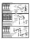
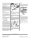
Figure 66
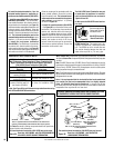
Remove the pilot orifice and replace it with the
one provided with the conversion kit. Reinstall
the pilot assembly by reversing the steps de-
tailed here.
When reinstalling the ignitor assembly, use
extreme care to prevent damage and break-
age. Do not apply any leverage to the ignitor
assembly while restoring the retainer clip to
its original position.
Note: If the ignitor is damaged, a replacement
kit is available - order Catalog Number 87L54.
All Models
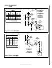
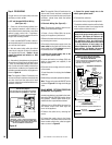
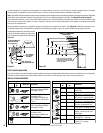
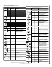
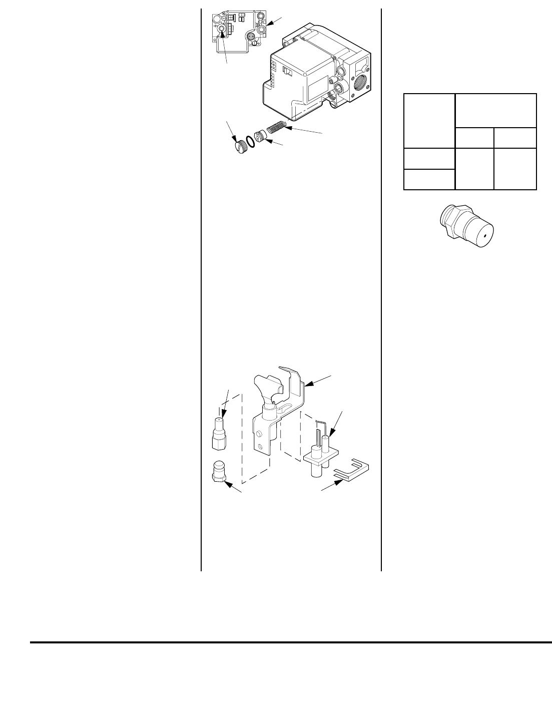
Step 7. Remove the orifice from the mani-
fold and replace it with the one provided with
the kit. See the following table for orifice sizes
for natural and propane models
. Figure 67
illustrates the orifice.
Figure 65
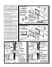
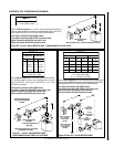
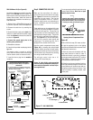
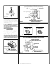
Step 6. Electronic Appliances -
Honeywell Systems
See
Figure 65
and the instructions provided
with the kit. Remove the slotted cap screw, o-
ring, pressure-regulating adjusting screw and
spring. Retain all parts for possible later use.
Install new components from the kit. Black cap
and red spring for propane gas units. Silver cap
and stainless steel spring for natural gas units.
Before installing the cap, attach manometer to
the manifold side pressure test fitting and adjust
screw until pressure reads 3.5 inches water
column (0.87 kPa) for natural gas, and 10.0
inches water column (2.49 kPa) for propane gas.
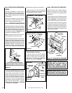
See
Figure 66
and replace the pilot orifice as
follows: Remove the ignitor assembly retainer
clip, and carefully remove the ignitor assembly.
Exercise extreme care to prevent damage to
or breakage of the ignitor assembly.
Remove the screw securing the pilot assembly
to its mounting bracket. Back off the flare nut
at the end of the pilot gas line to free the pilot
assembly from the gas line.
Spring
Adjusting
Screw
Slotted
Cap
P
S
I
OFF
I
ON
CONTROL
I
G
N
I
T
E
Manifold
Pressure
Test Port
Inlet Pressure Test Port
Retaining
Clip
Ignitor
Assembly
Pilot
Assembly
Pilot
Orifice
Flare Nut
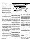
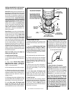
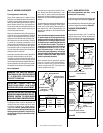
Use a 7/16" open end wrench and turn the pilot
hex fitting counter-clockwise 1/4 turn. (
refer
to
Figure 62 ).
e. Retighten, clockwise, the pilot hex fitting
until the pilot hood aligns with the thermo-
couple and thermopile as indicated by the
arrows shown in
Figure 62
.
Note - The orifice strip tab may be randomly
located on any side of the hex fitting.
d. Push the orifice strip tab all the way against
the hex fitting to align the appropriate gas type
orifice
(refer to Figures 63 and 64)
. The type
of gas for which the pilot is set, is, the gas type
shown on the tab.
b. Attach manometer to the manifold side
pressure test fitting and verify manifold pres-
sure reads 3.5 inches water column (0.87 kPa)
for natural gas, and 10.0 inches water column
(2.49 kPa) for propane gas.
c.
Convert the pilot orifice as follows (refer to
Figures 62, 63 and 64 ):
Note - Use extra care not to engage the orifice
strip with the 7/16" open end wrench (contact-
ing the orifice strip could cause strip distortion
rendering the pilot inoperative). Also avoid
wrench contact to any of the other pilot parts.
Figure 67
.oNledoM
ezisecifirO
larutaNenaporP
004-TD
54#
840.0
hcni
004-RD
Printed in U.S.A. © 2002 by Lennox Hearth Products
P/N 700,020M REV. M 11/2004
The manufacturer reserves the right to make changes at any time, without notice, in design, materials, specifications, prices and also to discontinue colors, styles and products.
Consult your local distributor for fireplace code information.
LHP
1110 West Taft Avenue • Orange, CA 92865
NOTE: DIAGRAMS & ILLUSTRATIONS NOT TO SCALE.