


5
NOTE: DIAGRAMS & ILLUSTRATIONS NOT TO SCALE.
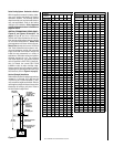
hctiPfooR
H
)teef(
21/6ottalF0.1
21/7ot21/6revO52.1
21/8ot21/7revO5.1
21/9ot21/8revO0.2
21/01ot21/9revO5.2
21/11ot21/01revO52.3
21/21ot21/11revO0.4
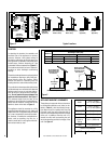
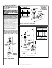
Right Side
Front Corner of
Fireplace Framing
6 ¹⁄₂"
(152 mm)
3"
(76 mm)
12
X
Roof Pitch is X/12
2 FT
MIN.
2 FT MIN.
Lowest
Discharge
Opening
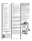
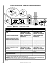
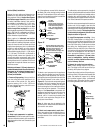
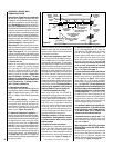
H*
*H = MINIMUM HEIGHT FROM ROOF TO
LOWEST DISCHARGE OPENING OF VENT
TERMINATION HEIGHTS FOR VENTS ABOVE
FLAT OR SLOPED ROOFS
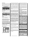
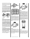
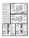
Horizontal Overhang
Vertical
Wall
Vent
Termination
Storm Collar
Concentric
Vent Pipe
Flashing
1 inch (25.4 mm) Minimum
Clearance to Combustibles
Figure 4
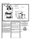
Figure 5 -
Side Elevation View
Figure 7
Horizontal Vent Termination Clearances
The horizontal vent termination must have a
minimum of 3" (76 mm) clearance to any
overhead combustible projection of 2 ¹⁄₂" (64
mm) or less. See
Figure 5.
For projections
exceeding 2 ¹⁄₂" (64 mm), see
Figure 5
. For
additional vent location restrictions refer to
Figure 7 on page 6
.
Terminate multiple vent terminations accord-
ing to the installation codes listed at the top of
this page.
Vertical Vent Termination Clearances
VENT TERMINATION CLEARANCES
These instructions should be used as a guide-
line and do not supersede local codes in any
way. Install vent according to local codes,
these instructions, the current National Fuel
Gas Code (ANSI-Z223.1) in the USA or the
current standards of CAN/CGA-B149.1 and -
B149.2 in Canada.
Terminate single vent caps relative to building
components according to
Figure 4
.
See
Figure 31
or 32 for the recess allowances,
into exterior walls, of the round and square
horizontal terminations.
Step 2. (page 5) Route gas supply line to
appliance location.
Step 3. (page 8) Install the vent system and
exterior termination.
Step 4. (page 20) Field Wiring
Millivolt Appliances – The operating control
switch is factory installed.
Step 5. (page 20) Install blower kit (optional
equipment).
Step 6. (page 21) Make connection to gas
supply.
Step 7. (page 22) Install the logs, vermicu-
lite and glowing embers.
Step 8. (page 22) Checkout appliance opera-
tion.
Step 9. (page 22) Install glass door frame
assembly.
Step 10. (page 23) Adjust burner to ensure
proper flame appearance.
Step 11. (page 23) Install the hoods.
Step 1. FRAMING
Frame these appliances as illustrated in
Fig-
ures 8 on page 7,
unless the appliance is to be
installed in a corner
.
See
Figure 9 on page 7
for corner framing installations. All framing
details must allow for a minimum clearance to
combustible framing members as shown in
Table 2 on page 4
.
If the appliance is to be elevated above floor level,
a solid continuous platform must be constructed.
Headers may be in direct contact with the appli-
ance top spacers but must not be supported by
them or notched to fit around them. All construc-
tion above the appliance must be self supporting,
DO NOT use the appliance for structural support.
Step 2. ROUTING GAS LINE
Route a ¹⁄₂" (13 mm) gas line along the inside of
the right side framing as shown in
Figure 7
.
Gas lines must be routed, constructed and
made of materials that are in strict accordance
with local codes and regulations.
All appliances are factory-equipped with a flex-
ible gas line connector and ¹⁄₂ inch shutoff
valve. (See step 6 on page 20).
TYPICAL INSTALLATION SEQUENCE
The typical sequence of installation follows,
however, each installation is unique resulting
in variations to those described.
See the page numbers references in the follow-
ing steps for detailed procedures.
Step 1. (page 5) Construct the appliance
framing. Position the appliance within the
framing and secure with nailing brackets.
DETAILED INSTALLATION STEPS
The appliance is shipped with all gas controls
and components installed and pre-wired. Re-
move the shipping carton, exposing the front
glass door. Remove the top panel. Remove
the cardboard from underneath the pressure
relief plates. Gently depress the outer top
corners of the access panel until the catches
"pop" the panel free, allowing it to swing out and
down to open. Open the two latches (located
under the firebox floor) securing the glass
door. Remove the door by tilting it outward at
the bottom and lifting it up. Set the door aside
protecting it from inadvertent damage.
See
Figure 50 on page 21.
Remove the two card-
board pad strips from between the firebox
subfloor and the firebox sides.
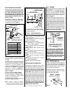
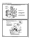
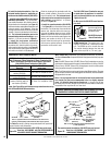
The fireplace should be secured to the side framing
members using the unit's nailing flanges - one top
and bottom on each side of the fireplace front. See
Figure 6.
Use 8d nails or their equivalent.
Figure 6
Note: The nailing flanges, combustible members
and screw heads located in areas directly adjacent
to the nailing flanges, are EXEMPT from the 1/2
”
clearance to combustible requirements for the
firebox outer wrapper. Combustible framing may be
in
direct contact with the nailing flanges and may
be located closer than 1/2
” from screw heads and
the firebox wrapper in areas adjacent to the nailing
flanges. Frame the opening to the exact dimensions
specified in the framing details of this manual.
Side
Framing
Unit Nailing Flange
(No clearance to
combustible
framing is required)
Left Side Front Corner of Fireplace Shown
(Right Side Requirements the Same)
Unit Being Secured By Its Nailing Flanges
To The Framing
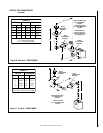
3"
(76 mm)
12"
(305 mm)
Termination Kit
Combustible Projection
greater than 2¹⁄₂ inches in length
Horizontal Vent Termination Clearances
Combustible Projection
2¹⁄₂ inches or less in length
18"
(457 mm)
Ventilated
Soffit
Unventilated
Soffit