


20
NOTE: DIAGRAMS & ILLUSTRATIONS NOT TO SCALE.
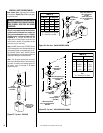
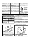
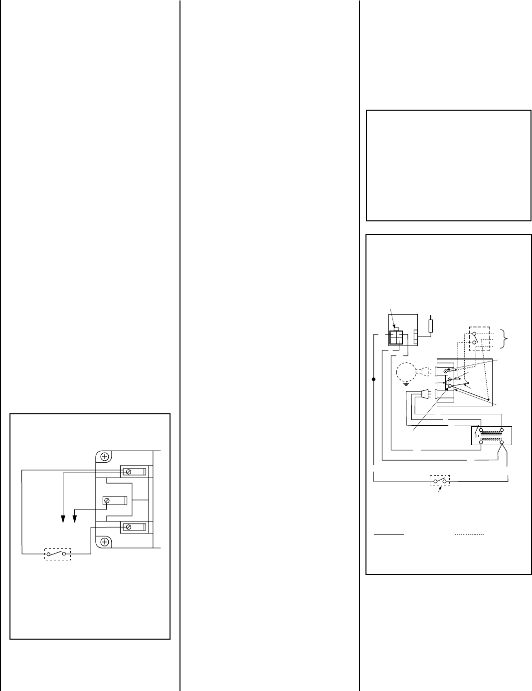
1. If any of the original wire as supplied must be replaced,
1. it must be replaced with Type AWM 105°C – 18 GA. wire.
2. 120V, 60Hz – Less than 3 amps.
BK
Junction Box
Transf.
120 V.
24 V
Factory Wired Field Wired
BL
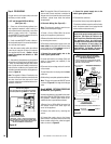
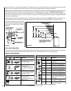
Electronic Wiring Diagram (Honeywell)
Showing the Blower Wiring for the Optional
FBK-100 and FBK-200 Kits
R
W
BL
OPT
BLOWER
G
W
*OPTIONAL
ACCESSORY
SWITCH
120
VAC.
BK
W
Gas Valve
B
R
IGNITER
PILOT
ASSEMBLY
Break Off
Tab
BK
G
*Blower speed control switch is provided in FBK200 blower kit.
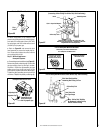
Outlet Box
Green Ground
Screw
Hot side of Outlet
Schematic Representation Only
**ON/OFF Switch (Integral
with Gas Valve)
**Leave the ON/OFF switch, which is integral
with the gas valve, in the ON position.
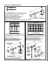
OPTIONAL APPLIANCE-MOUNTED ON/OFF SWITCH
OR OPTIONAL WALL SWITCH
OR OPTIONAL THERMOSTAT
OR OPTIONAL REMOTE RECEIVER
Red
pigtail
Black
pigtail
White Wire
to Opposite
Side
G
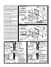
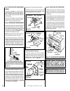
4. Connect the ground supply wire to the
outlet's green ground screw.
5. Reinstall the outlet box.
6. Insert the blower plug into the top outlet.
(The bottom outlet is unused on millivolt units,
while the burner control circuit plugs into the
bottom outlet on electronic units.)
Figure 45
IMPORTANT: Ground lead must be con-
nected to the green screw located on the
outlet box. See
Figure 45
. Failure to do
so will result in a potential safety hazard.
The appliance must be electrically
grounded in accordance with local codes
or, in the absence of local codes, the
National Electrical Code, ANSI/NFPA 70-
(latest edition). (In Canada, the current
CSA C22-1 Canadian Electrical Code.)
Note: The supplied 15 feet of 2 conductor wire
has one end of each conductor connected to
the gas valve circuit and the other end of each
conductor placed loose inside the bottom
compartment.
B. Electronic Wiring (See
Figure 45
) –
Note: The electronic appliance must be con-
nected to the main power supply.
1. Route a 3-wire 120Vac 60Hz 1ph power
supply to the appliance junction box.
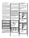
2. Remove the outlet box from the junction box
by removing two screws .
3. Connect the black power supply wire to the
lower outlet's red pigtail lead and the white
power supply wire to the common terminal of
the outlet as shown in
Figure 46.
4. Connect the ground supply wire to the
outlet's green ground screw.
5. Locate and install a low voltage (24V) wall
switch or thermostat (not supplied) in the
desired location.
6. Connect the low voltage wire to this switch
or thermostat.
7.
Insert the control circuit plug into the lower
outlet box.
8. After wiring is complete, replace the outlet box.
Note: The gas valve-mounted ON/OFF switch
is shown in Figure 45. It is integral with the gas
valve.
Step 5. WIRING - OPTIONAL FORCED AIR
BLOWER KIT (See
Figure 45 )
An electrical outlet box is provided for the instal-
lation of the FBK-100, FBK-200 forced air blower
kits (optional). Electrical power must be pro-
vided to this box to operate these blowers.
1. Route a 3-wire, 120Vac 60Hz 1ph power line
with control switch to the lower right rear
corner of the appliance.
2. Remove the outlet box by removing two
screws.
3. Connect the supply wires to the blower
control switch. Then connect the wires from the
blower control switch to the outlet box' pigtail
leads as shown in
Figure 45
.
Step 4. FIELD WIRING
The gas valve is set in place and pre-wired at
the factory on both models.
A. SIT and Honeywell Millivolt Wiring
(See Figure 44 )
–
1. Select any of the following optional con-
trols: appliance-mounted (rocker switch) or
wall-mounted switch, thermostat, or one of the
optional remote control kits. If appliance-
mounted ON/OFF control is selected mount it in
the gas valve mounting bracket.
2. If wall-mounted ON/OFF control or thermo-
stat is selected mount it in a convenient location
on a wall near the fireplace.
3. Wire the control switch within the millivolt
control circuit using the 15 feet of 2 conductor
wire supplied with the unit. Caution: do not
connect the optional wall switch to a 120V
power supply.
4. Alternatively, the appliance may be operated
without the use of the controls indicated in step
1, solely by manipulating the gas valve control
knob. In order to use this method, twist the free
ends of the two conductor wire (located inside
the bottom compartment of the unit) together as
shown in
Figure 44
.
Note: The supplied 15 feet of 2 conductor wire
has one end of each conductor connected to the
gas valve circuit and the other end of each
conductor placed loose inside the bottom com-
partment of the unit.
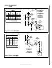
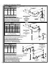
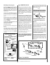
Figure 44
Millivolt Wiring Diagram
If any of the original wire as supplied must be replaced,
it must be replaced with Type AWM105°C – 18 GA. wire.
Thermopile
TH
TP
TH
TP
*TWIST WIRES “A” AND “B” TOGETHER TO OPERATE UNIT
SOLELY BY MANIPULATING THE GAS VALVE CONTROL KNOB;
OR CONNECT WIRES TO OPTIONAL ON/OFF SWITCH OR WALL
SWITCH OR THERMOSTAT TO OPERATE UNIT.
*OPTIONAL ON/OFF SWITCH,
WALL SWITCH, THERMOSTAT
OR REMOTE CONTROL RECEIVER
AB