


23
NOTE: DIAGRAMS & ILLUSTRATIONS NOT TO SCALE.
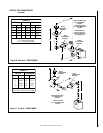
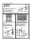
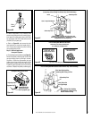
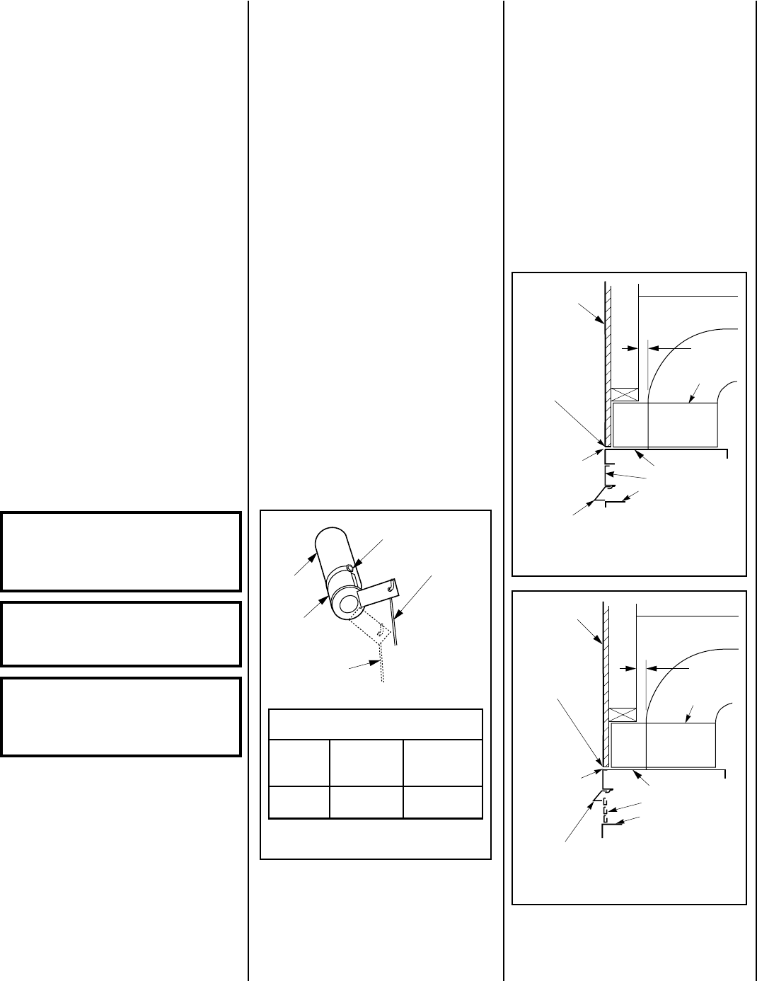
Adjustment Rod Up
(Fully Open Position)
Air Shutter
Burner Tube
Adjusting Set Screw
Adjustment Rod Down
(minimum air
opening position)
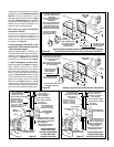
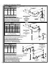
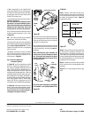
Combustible
Finished Wall
Materials
This Area Must Remain
Clear of Combustible
Materials
Top of Appliance
1" Min
(25 mm)
Spacer
Clean Face Models
Top of Door Frame
Hood must be installed as shown.
Radiant panel
Combustible
material
may touch the
appliance top.
Combustible
materials not
allowed below
this point on
the face of the
appliance.
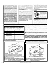
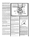
Combustible
Finished Wall
Materials
This Area Must Remain
Clear of Combustible
Materials
Top of Appliance
1" Min
(25 mm)
Spacer
Louver Face Models
Top of Door Frame
Combustible
material
may touch the
appliance top.
Hood must be installed as shown.
Louvers
Combustible
materials not
allowed below
this point on
the face of the
appliance.
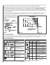
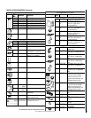
RIAYROTCAF
GNITTESRETTUHS
sledoM
saGlarutaN
sehcni
)mm(
saGenaporP
sehcni
)mm(
004-TD
004-RD
23/1
)8.0(
61/5
)0.8(
Figure 54
Figure 55
Figure 56
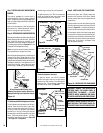
FINISHING REQUIREMENTS
Wall Details
Complete finished interior wall. To install the
appliance facing flush with the finished wall,
position framework to accommodate the thick-
ness of the finished wall (
Figures 55 and 56
).
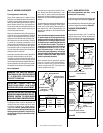
Step 11. HOOD INSTALLATION
All of these appliances must have hoods
installed prior to operating.
On all clean face units, slide the hood into the slots
on the lower edge of the radiant panel (
Figure 55
).
On louvered face units, slide the hood into the slots
on the lower edge of the cabinet top (
Figure 56
).
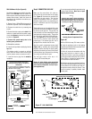
Burner Adjustment
WARNING: AIR SHUTTER ADJUST-
MENT SHOULD ONLY BE PERFORMED
BY A QUALIFIED PROFESSIONAL
SERVICE TECHNICIAN.
IMPORTANT: ENSURE THAT THE
FRONT GLASS PANEL IS IN PLACE
AND SEALED DURING ADJUSTMENT.
CAUTION: THE AIR SHUTTER DOOR AND
NEARBY APPLIANCE SURFACES ARE HOT.
EXERCISE CAUTION TO AVOID INJURY
WHILE ADJUSTING FLAME APPEARANCE.
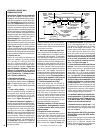
Step 10. BURNER ADJUSTMENTS
Flame Appearance and Sooting
Proper flame appearance is a matter of taste.
Generally, most people prefer the warm glow of
a yellow to orange flame. Appliances operated
with air shutter openings that are too large will
exhibit flames that are blue and transparent.
These weak, blue and transparent flames are
termed anemic. If the air shutter opening is too
small sooting may develop.
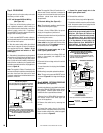
Sooting is indicated by black puffs developing
at the tips of very long orange flames. Sooting
results in black deposits forming on the logs,
appliance inside surfaces and on exterior sur-
faces adjacent to the vent termination. Sooting
is caused by incomplete combustion in the
flames and lack of combustion air entering the
air shutter opening. To achieve a warm yellow
to orange flame with an orange body that does
not soot, the shutter opening must be adjusted
between these two extremes.
No smoke or soot should be present. Reposition
the logs if flames impinge on any of them.
If the logs are properly positioned and sooting
conditions exist, the air shutter opening on the
main burner tube should be adjusted. Normally,
the more offsets in the vent system, the greater
the need for the air shutter to be opened further.
Allow the burner to operate for at least 15 min-
utes. Observe the flame continuously. If it ap-
pears weak or sooty as previously described,
adjust the air shutter by pushing or pulling on the
adjustment rod until the flame appearance is as
desired.
The adjustment rod and associated adjustable air
shutter is patented technology. Flame adjust-
ments can be made quickly and accurately to
taste without the need of disassembling the
appliance and waiting for 30 minutes after each
adjustment.
Note: If the flame still appears anemic with the
air shutter closed all the way against the stop
(usually a result of lengthy vertical runs), turn
the appliance off, turn the gas supply off, wait
for the parts to cool, remove the glass door and
logs to access the air shutter. The shutter is
prevented from actually closing all the way by
an adjustment set screw (see Figure 54). Re-
move this screw using a
¹⁄₄
inch nut driver.
Reinstall the logs and glass door, turn the gas
back on and then restart the appliance. After 30
minutes, reobserve the flame. Adjust the air
shutter as previously described.
When satisfied that the appliance operates
properly, proceed to finish the installation.
Leave the control knob in the ON position
and the remote switch OFF. Close the lower
control compartment door.
To adjust the flame, move the adjustment rod
(located in the lower control area) up or down
to increase or reduce the air shutter opening,
respectively. Initially, always position the air
shutter to the factory setting (the minimum air
opening position) as shown in
Figure 54
. This
can be done by pulling the adjustment rod all
the way down.