


16
NOTE: DIAGRAMS & ILLUSTRATIONS NOT TO SCALE.
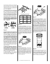
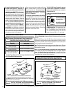
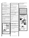
SFHRK Snorkel Cap –The snorkel cap is de-
signed to be fitted into a basement window
box. The SFHRK cap is for use with flex vent
The vertical distance between the inlet and
outlet of the cap is 28 in. (711 mm). pipe.
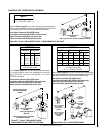
*Note: See Figure 35 for wall thickness range reductions when using
SV4.5HTS and SV4.5HTSS terminations.
Figure 35
-
Figure 34
-
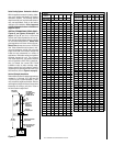
See
Table 3
as an aid in venting component selection for a particular
range of exterior wall thicknesses.
HORIZONTAL VENT FIGURES/TABLES
Note: Two 45 degree elbows may be used in place of one 90 degree elbow. The same
rise to run ratios, as shown in the venting figures for 90 elbows, must be followed if
45 degree elbows are used.
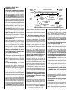
Note: It is very important that the horizontal/inclined run be maintained
in a straight (no dips) and recommended to be in a slightly elevated
plane, in a direction away from the fireplace of
¹⁄₄
" rise per foot (20 mm
per meter) which is ideal, though rise per foot run ratios that are smaller are
acceptable all the way down to at or near level.
The round horizontal termination (SV4.5HTR) may not be used.
WARNING: UNDER NO CIRCUMSTANCES MAY SEPARATE SECTIONS
OF CONCENTRIC FLEXIBLE VENT PIPE BE JOINED TOGETHER.
The round horizontal termination (SV4.5HTR) may not be used.
Note: Secure Vent components (rigid vent pipe and terminal) are shown in
the figures; Secure Flex components (flexible vent pipe and terminal) may also
be used.
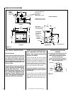
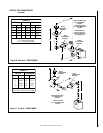
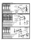
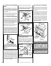
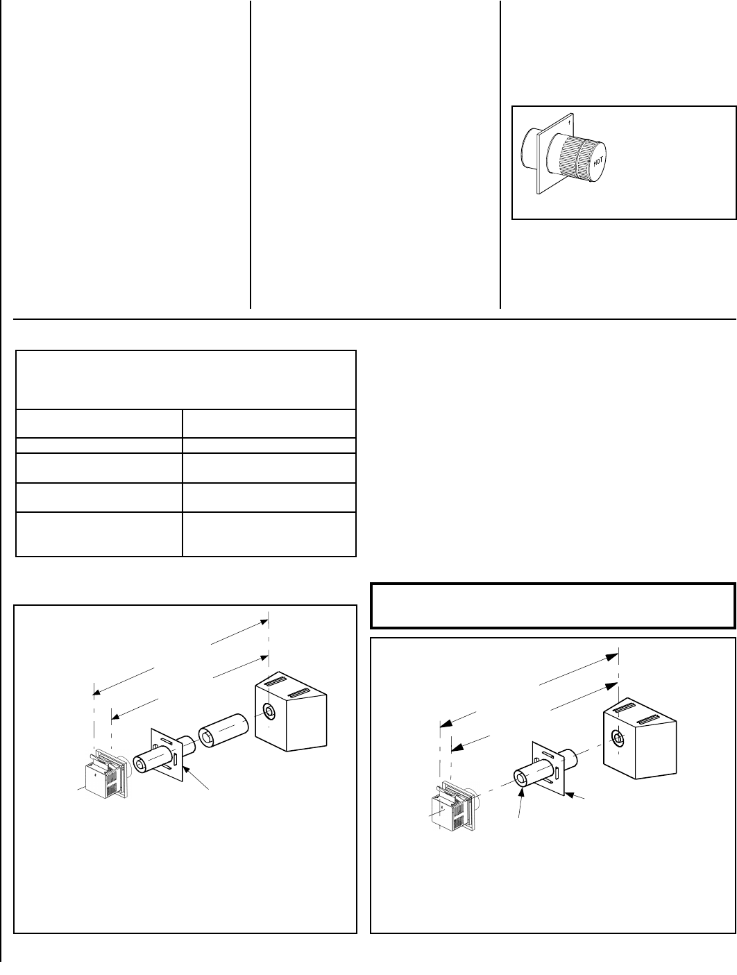
Rear Vent - NO ELBOWS - with SV4.5HTS SQUARE OR
SV4.5HTSS SHORT SQUARE TERMINATION
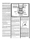
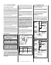
Rear Vent - NO ELBOWS - with SV4.5HTSSL
LONG SQUARE TERMINATION
Note: SV4.5BF (Secure Vent), SF4.5BF (Secure Flex) firestop/spacer must be
used anytime vent pipe passes through a combustible floor or ceiling. SV4.5HF
(Secure Vent), SF4.5HF (Secure Flex) firestop/spacer must be used anytime
vent pipe passes through a combustible wall.
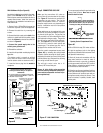
roiretxEsuoiraVrofderiuqeRstnenopmoCgnitneV-3ELBAT
-stiKnoitanimreTesehTfoynAgnisUnehW,sessenkcihTllaW
noitanimreTerauqSllamS)STH5.4VS(noitanimreTerauqS
)RTH5.4VS(noitanimreTdnuoR)SSTH5.4VS(
stnenopmoCgnitneV
deriuqeR
sessenkcihTllaWroiretxE
mm(sehcni )
ylnOtiKnoitanimreT64/101ot)062ot251(
tnev.ni6dnatiKnoitanimreT
)6L5.4VS(noitces
)573ot062(4/341ot4/101
tnev.ni21dnatiKnoitanimreT
)21L5.4VS(noitces
)725*ot524(4/302*ot4/361
cipocseleTdnatiKnoitanimreT
.ni6dna)AL5.4VS(noitces
)6L5.4VS(noitcestnev
)255*ot892(4/312*ot4/311
*Wall Firestop/Spacer
(SV4.5HF)
28 in. (711 mm)
Maximum
Note - In applications where the wall thickness is less than 6 inches
(152 mm), field shortening of the termination collar may be required.
SV4.5HTSS Termination Shown
20 in. (508 mm)
Maximum
*When using Secure Flex,
use Firestop/Spacer
(SF4.5HF)
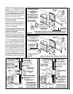
*Wall Firestop/Spacer
(SV4.5HF)
28 in. (711 mm)
Maximum.
Note - It may be necessary to cut the termination collar
in some applications.
10³⁄₄ to 20 in.
(273 to 508 mm)
12 in. Vent Section
(SV4.5L12)
*When using Secure flex,
use Firestop/Spacer
SF4.5HF)
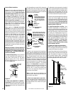
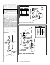
Do Not recess the SV4.5HTR round termina-
tion at all.
See Horizontal Venting
Figures and Tables for
Use Restrictions
SV4.5HTR Horizontal
Round Termination
Figure 33
3. Install the round termination (SV4.5HTR)
– See
Figure 33
for an illustration of the round
termination. For the last step, from outside the
exterior wall, slide the collars of the termina-
tion onto the adapter (same as shown in
Fig-
ure 31
for the SV4.5HTSS short square termi-
nation) until the termination seats against the
exterior wall surface to which it will be at-
tached. Orient the housing of the termination
with the arrow pointed upwards. Secure the
termination to the exterior wall.
M. Install the desired termination - See the
horizontal venting figures for application re-
strictions on the round termination (SV4.5HTR).
1. Install the square (SV4.5HTS) or short square
termination (SV4.5HTSS) - For the last step ,
from outside the exterior wall, slide the collars of
the termination into the adapter (see
Figure 31
)
until the termination seats against the exterior wall
surface to which it will be attached. Orient the
housing of the termination with the arrow pointed
upwards. Secure the termination to the exterior
wall. The horizontal termination must not be
recessed into the exterior wall or siding by more
than the 1 ¹⁄₄" (32 mm) as shown in
Figure 31
.
Orient the housing of the termination with the
arrow pointed upwards. Secure the termina-
tion to the exterior wall. The horizontal termi-
nation must not be recessed into the exterior
wall or siding by more than the 1 ¹⁄₄" (32 mm)
as shown in
Figure 32
.
The SV4.5HTR Round Termination may not
be used when the appliance is vented di-
rectly out the wall from the rear as shown in
Figures 34 and 35
.
2. Install the long square termination
(SV4.5HTSSL) - For the last step , from outside
the exterior wall, slide the collars of the termi-
nation onto the last vent section (see
Figure 32
)
until the termination seats against the exterior
wall surface to which it will be attached.