


NOTE: DIAGRAMS & ILLUSTRATION NOT TO SCALE.
9
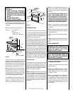
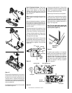
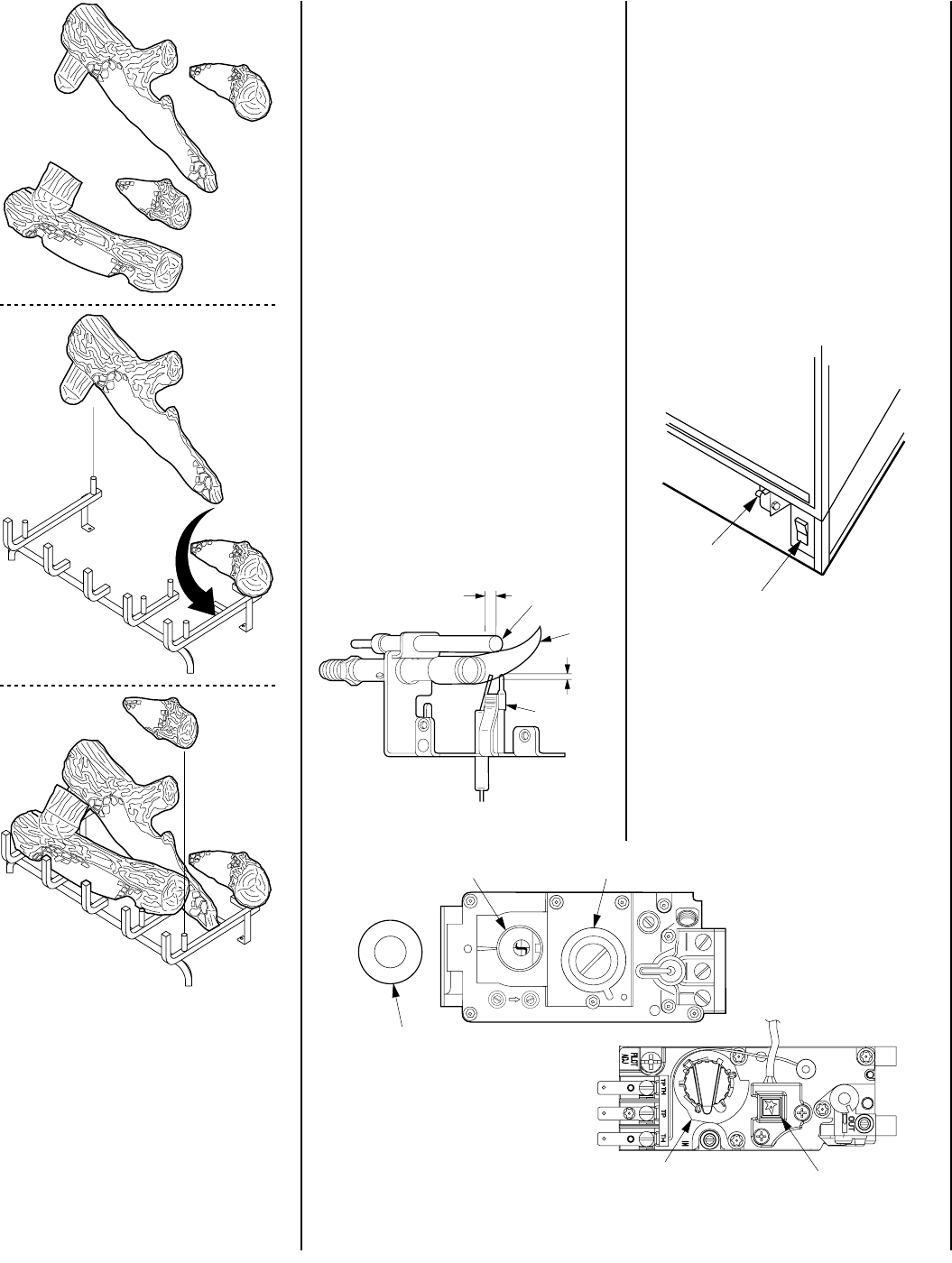
Figure 18
Step 10. Checking the System – After the gas
line is installed, logs are in place and the
system is leak checked, run initial system
checkout before closing up the front of the
unit. Follow the pilot lighting instructions on
pages 16 and 17.
Note: Instructions are also found on the pull out
panel located on the bottom surface of the
appliance.
When first lighting the appliance, it will take a
few minutes for the line to purge itself of air.
Once purging is complete, the pilot and burner
will light and operate as indicated in the in-
struction manual.
Subsequent lightings of the appliance will not
require such purging. Inspect the pilot flame
(remove logs, if necessary, handling carefully).
The flame should be steady, not lifting or float-
ing. Flame should be blue in color with traces
of orange at the outer edge.
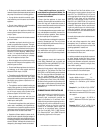
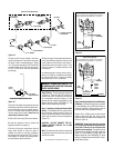
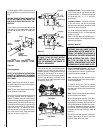
For natural gas units the last ³⁄₈" (10 mm) of the
pilot generator (thermopile) and the top ¹⁄₈" (3.2
mm) min (tip) of the quick drop out thermo-
couple should be engulfed in the pilot flame
(
Figure 19
).
b.
a.
b.
a.
c.
d.
c.
d.
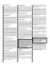
Figure 20
³⁄₈"
Min
¹
⁄₈"
Min
Natural
Shown
Thermopile
Thermocouple
Pilot
Flame
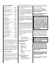
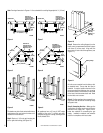
Position the front log assembly (c) over the pin
located at the front of the left log rack bar and
the back pin of the short (second from the
right) log rack bar. Install the remaining right
front log (d) over he last two pins located at the
front of the right log rack bar and the short log
rack bar respectively.
The installation of the logs should be complete
and resemble
Figure 18
.
Figure 19
On propane models the last ³⁄₈" (10mm) of the
pilot generator should be engulfed in the pilot
flame. The propane thermocouple is attached
to the side of the pilot burner tube.
Replace logs if removed for pilot inspection.
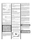
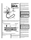
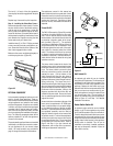
To light the pilot, manually depress and hold the
door safety switch (
Figure 21
) and rotate the
control knob counterclockwise to the “PILOT”
position and press in and light by pressing the
piezo button (refer to lighting instructions on
page 17 and
Figure 20
).
Note: The door safety switch must be held
closed and the rocker switch must be "ON" for
burner operation (Figure 21 ).
Door
Swtich
Rocker Swtich
(Optional)
Figure 21
To obtain proper operation, it is imperative
that the main burner characteristics are steady.
The flame should produce a clear, bright or-
ange/yellow flame. No smoke or soot elements
should be visible. If questionable, check with
your service man or gas supplier. The flames
should not impinge on the logs, reposition
them if necessary.
EA
TPTH TP TH
P
I
L
O
T
P
I
L
O
T
O
N
it
O
F
F
SIT Millivolt
Valve
Gas Control Knob
Piezo Ignitor
Flame Adjustment Knob
Honeywell
Millivolt Valve
Gas Control Knob
Spark Ignitor
O
N
O
F
F
P
I
L
O
T
L
O
H
I