


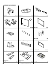
NOTE: DIAGRAMS & ILLUSTRATION NOT TO SCALE.
10
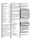
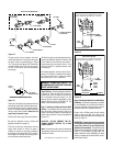
Rear Burner Flames – The rear flames rising in
front of center and rear logs should be yellow
and extend about 2 ¹⁄₂ – 3" above the large logs
for natural gas and 1 ¹⁄₂ – 2 ¹⁄₂” above for
propane gas.
Front Burner Flames – The flames at the front
of the main burner will be blue becoming
yellowish as they hit the bark-like texture on the
front face of the front base log.
Low flame setting observable characteristics
are approximately 2" to 2 ¹⁄₂” shorter than the
flames are on high.
Refer to the Operation and Maintenance in-
structions on page 12 of this manual for flame
adjustment procedures.
Figure 22
Flame Appearance
REFER TO THE OPERATING INSTRUCTIONS
LOCATED AT THE BACK OF THIS MANUAL
BEFORE LIGHTING THE HEATER TO OBSERVE
THE FLAMES.
Note: Instructions are also found on the pull-
out panel located in the l ower control compart-
ment of the appliance.
Note: The door switch must be held closed for
burner operation when testing.
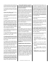
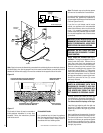
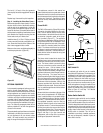
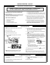
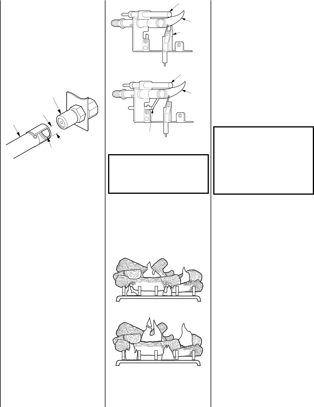
Flames from the pilot and main burner should
be visually checked when the appliance is
installed. In addition a periodic visual check of
the flames should be made throughout the life
of the appliance. The pilot flame should always
be present when the heater is in operation and
should just envelope the tip of the thermo-
couple (
Figure 23
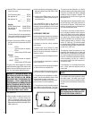
). The main burner flames
must not impinge on the logs with the excep-
tion of the charred areas, flame appearance
should be as shown in
Figure 24
.
Figure 23
WARNING: NO ADJUSTMENTS ARE TO
BE MADE TO THE ODS PILOT SYSTEM.
TAMPERING WITH THIS SYSTEM WILL
VOID THE WARRANTY AND CAN BE EX-
TREMELY HAZARDOUS.
A pilot flame that does not envelope the ther-
mocouple tip, will cause the main burner to
function improperly. If the pilot flame does not
envelope the thermocouple tip as shown in
Figure 23
, contact your service representative.
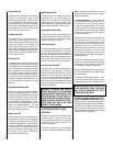
In normal operation after 15 minutes the fol-
lowing main burner flame appearance should
be observed (
Figure 24
).
The flame height and BTU input may be altered
by rotating the flame control valve from low to
high.
CAUTION: DO NOT ATTEMPT TO REDUCE OR
ALTER THE FLAME BY POSITIONING THE
GAS VALVE IN OTHER THAN THE FULL “ON”
POSITION.
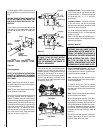
The air shutter on the venturi tube has been set
at the factory for both natural and propane gas
models, refer to
Figure 22
for air shutter set-
tings.
Low Flame
High Flame
Figure 24
Natural Pilot
Propane Pilot
Thermopile
Thermocouple
Thermopile
Thermocouple
Pilot
Flame
Pilot
Flame
Appliance Operation
WARNING: THE LOWER CONTROL COM-
PARTMENT AREA AND LOWER CONTROL
COMPARTMENT ACCESS DOOR ARE EX-
TREMELY HOT WHEN THE APPLIANCE IS
IN OPERATION. EXERCISE EXTREME CARE
WHEN ACCESSING THIS AREA. TOUCH
ONLY THE FAR ENDS OF THE LOWER
CONTROL COMPARTMENT DOOR WHEN
OPENING WHILE THE APPLIANCE IS HOT.
Orifice
Burner
Manifold
Air Shutter
Opening
Air Shutter
Opening
(Not Adjustable)
Natural Gas - ¹⁄₁₆" Open
Propane Gas - ¹⁄₈" Open
Natural Gas - ¹⁄₁₆" Open
Propane Gas - ³⁄₁₆" Open
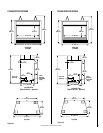
CF-5500
CF-6500
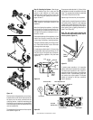
Step 11. Checking the System – With gas line
installed run initial system checkout before
closing up the front of the unit. Follow the pilot
lighting instructions on pages 17.
Note: Instructions are also found on the pull
out panel located in the lower control compart-
ment of the appliance.
To light the burner; turn “ON” the optional
remote wall switch (if installed) and rotate the
gas valve control knob counterclockwise to the
“ON” position.
Note: The door switch must be held closed for
burner operation when testing.
When first lighting the appliance, it will take a
few minutes for the line to purge itself of air.
Once purging is complete, the pilot and burner
will light and operate as indicated in the instruc-
tion manual. Subsequent lightings of the appli-
ance will not require such purging. Inspect the
pilot flame (remove logs, if necessary, handling
carefully).
The pilot flame should be steady, not lifting or
floating. Flame should be blue in color with
traces of orange at the outer edge.