


NOTE: DIAGRAMS & ILLUSTRATION NOT TO SCALE.
7
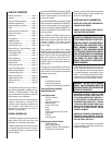
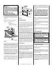
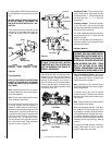
The gas control valve is located in the lower
control compartment. To access the valve open
the lower control compartment door (
Figure
13
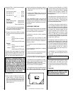
). The control valve has a ³⁄₈" NPT thread inlet
port and is fitted with a 3" (76 mm) long nipple,
³⁄₈" NPT on both ends. Plan the connections
accordingly.
D. When the gas lines are tested and leak free,
observe the individual tongues of flame on the
burner. Make sure all ports are open and pro-
ducing flame evenly across the burner. If any
ports are blocked, or partially blocked, clean
out the ports.
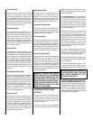
An external regulator must be used on all pro-
pane (L.P.G.) heaters, in addition to the regula-
tor within the gas valve, to reduce the supply
tank pressure to 13" w.c. (maximum).
WARNING: CONNECTING DIRECTLY TO
AN UNREGULATED PROPANE TANK CAN
CAUSE AN EXPLOSION.
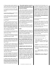
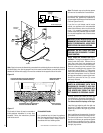
Step 6. Wiring – The wiring diagram is detailed
in
Figure 14
. Refer to
Figure 15
to field wire
optional wall switch. All electrical wiring must
be in accordance with local codes or, in the
absence of local codes the latest edition of the
National Electrical Code, ANSI/NFPA 70. The
heater must be electrically grounded.
Step 7. Installing the Optional Remote Wall
Switch – The standard millivolt system comes
from the factory wired as shown in
Figure 14
.
Select a convenient location for the remote wall
switch and connect the wiring to the appliance
(
Figure 15
).
CAUTION: DO NOT CONNECT THE OP-
TIONAL REMOTE SWITCH TO A 120V
POWER SUPPLY.
Note: The optional rocker switch is mounted to
the appliance and wired in the same way as the
remote wall switch.
Figure 12
Control
Valve
Lower Control
Compartment Door
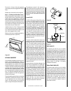
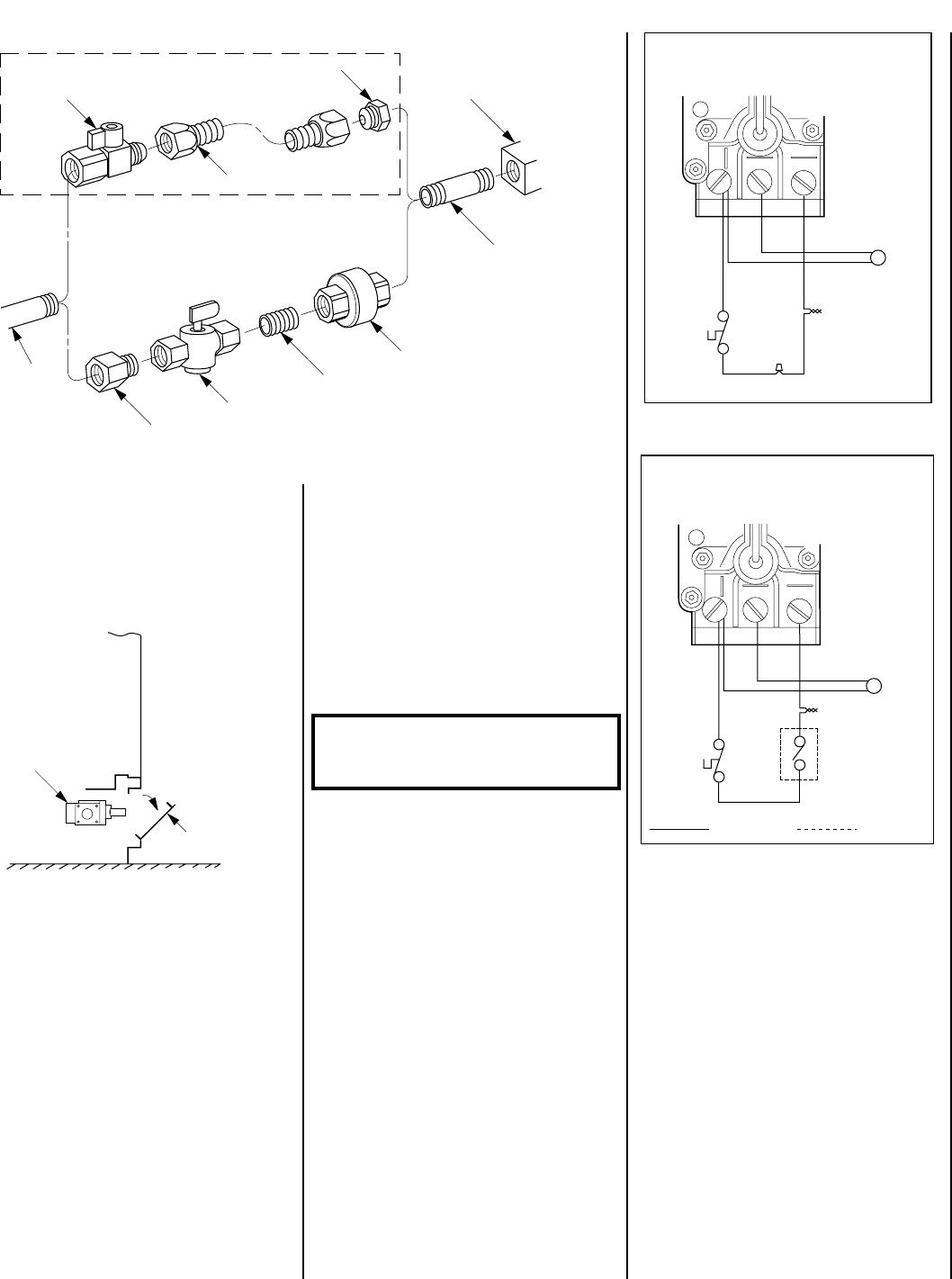
Figure 15
Standard Wiring Diagram
If any of the original wire as supplied must be replaced, it
must be replaced with Type AWM 105°C – 18 GA. wire.
Door
Switch
Thermopile
TPTH TP TH
Red
Wht
Red
Blu
* For On/Off Switch Attachment.
*
Blk
Blk
Optional Wiring Diagram
If any of the original wire as supplied must be replaced, it
must be replaced with Type AWM 105°C – 18 GA. wire.
Optional
ON/OFF
Rocker
Switch
Door
Switch
Thermopile
TPTH TP TH
Red
Blk
Wht
Red
Blu
Factory Wired
Field Wired
Figure 14
Step 8. Installing the Optional Forced Air Blower
Kit Wiring – An electrical outlet box is provided
for the installation of the FAB-1100 forced air
blower kit (optional). Electrical power must be
provided to this box to operate the blower.
Route a 3-wire, 120Vac power line with control
switch to the lower right rear corner of the
appliance. Make connections to the receptacle as
shown in
Figure 16
.
IMPORTANT: Ground lead must be connected
to the green screw located on the junction box
cover plate. Failure to do so will prevent the
appliance from operating. The appliance must
be electrically grounded in accordance with local
codes or, in the absence of local codes, the
National Electrical Code, ANSI/NFPA 70- latest
edition. (In Canada, the current CSA C22-1 Cana-
dian Electrical Code.)
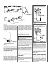
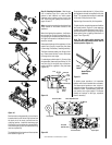
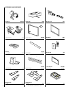
Gas Stub
¹₂" x ³₈" Flare
Shut-Off Valve
³₈" Flex Tubing
³₈" NPT x ³₈"
Flare Fitting
³₈" Nipple, Standard
with all Units
³₈" Union
³₈" Close Nipple
³₈" Shut-Off Valve
¹₂" x ³₈" Reducer
Gas Valve
Gas Flex Line Kit, Model GFLV
Figure 13
Secure all joints tightly using appropriate tools
and sealing compounds (ensure propane resis-
tant compounds are used in propane applica-
tions). Turn on gas supply and test for gas leaks
using a soapy water solution. Never use an
open flame to check for leaks.
A. Mix a 50% dish soap, 50% water solution.
B. Light the appliance (refer to safety and
lighting instructions on page 17).
C. Brush all joints and connections with the
soapy water solution to check for leaks. If
bubbles are formed, or gas odor is detected,
turn the gas control knob to the “OFF” position.
Either tighten or refasten the leaking connec-
tion and retest as described above.