


NOTE: DIAGRAMS & ILLUSTRATION NOT TO SCALE.
8
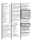
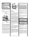
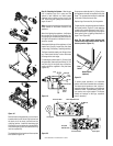
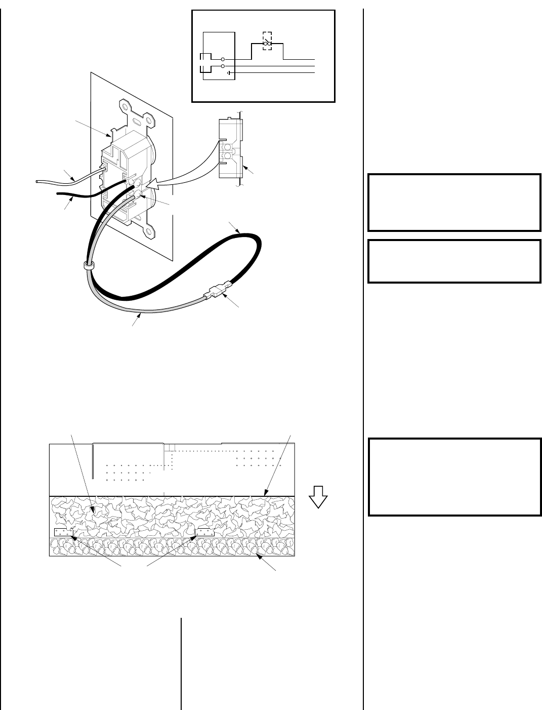
Figure 16
Note: Supply wires may be alternatively connected to the outlet using the screw terminals, however
the black supply wire must be ganged wired to the same terminal that the pre-wired black wire is
attached to and the white supply wire must be connected to the opposite side of the outlet.
White
(Supply)
Black
(Supply)
Bipolar
Terminal
Screw
Blower
(Lower)
Outlet
Black
Wire
Mating
Connectors
Red Wire
120 Vac
60 Hz
Blower Wiring Diagram
}
OFF/ON Blower
Wall Switch
To Fuse or
Circuit Breaker
120V
AC
60Hz
Fireplace
Junction Box
Black
White
Receptacle
Ground Wire
Connection
WARNING: FAILURE TO POSITION THE
PARTS IN ACCORDANCE WITH THESE
DIAGRAMS OR FAILURE TO USE ONLY
PARTS SPECIFICALLY APPROVED WITH
THIS HEATER MAY RESULT IN PROP-
ERTY DAMAGE OR PERSONAL INJURY.
WARNING: DO NOT PLACE ANY LAVA
ROCK ON LOGS OR BURNERS. THIS MAY
CAUSE SOOTING.
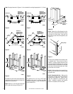
Note: The header may rest on the top spacers
but must not be notched to fit around them.
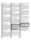
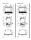
In order to install the appliance facing flush with
the finished wall, position the framework to
accommodate the thickness of the finished wall
(
Refer to Figures 2 and 3
).
If you live in a cold climate, seal all cracks
around your appliance with noncombustible
material and wherever cold air could enter the
room. It is especially important to insulate
outside chase cavity between studs and under
floor on which appliance rests, if floor is above
ground level.
WARNING: DO NOT ADD EXTRA LOGS OR
ORNAMENTS SUCH AS PINE CONES, VER-
MICULITE OR ROCK WOOL. USING THESE
ADDED ITEMS CAN CAUSE SOOTING.
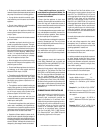
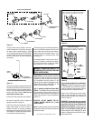
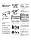
Step 9. Ember Coal, Rockwool and Log In-
stallation – The logs are packaged in a carton
packed inside the firebox. Remove the ce-
ramic fiber coals from their packaging and
spread evenly in the area in front of the burner.
Place the rockwool over the front half of the
burner ports, avoiding the two groups of five
larger holes (
refer to Figure 17
). Place ember
coals in the confined area in front of the burner
and behind the appliance front lip. Reinstall
the log grate removed in preparing the insert.
Secure the grate with the two (2) screws
previously removed.
Figure 17
Burner
Top View
Ember Chunks In
This Confinement
No Rockwool Material
Behind This Point
Keep Both Of These Five Hole Pattern
Areas Free Of Rockwool Materials
Front
Evenly Spread Dime Sized Pieces Of Rockwool
Over 85% Of This Area (Small Burner Holes)
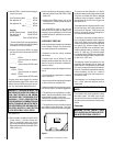
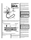
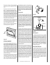
Carefully position and center the fiber logs
onto the burner in the manner illustrated (
Fig-
ure 18
). Positioning pins indicate log location.
The flames should not impinge on the logs.
Install the logs beginning with the right rear
log first (a). Engage it as shown over the pin
located at the back of the right log rack bar
(
Figure 18
).
Next, install the main log assembly (b) over the
pin located at the back of the left log rack bar.
The charred right nose of the main log rests
directly on the burner pan positioned against
the extension protruding from the right log
rack bar, and the end of the short (second from
the right) log rack bar.
The forced air blower kit may be mounted at
initial appliance installation or at any time
thereafter. Follow the instructions provided
with the blower kit.
Finished Wall Details
It is sometimes best to frame the appliance
after it has been positioned in place. Frame with
2 x 4s or heavier lumber. Always frame in
accordance with local building codes.