


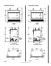
NOTE: DIAGRAMS & ILLUSTRATION NOT TO SCALE.
11
The appliances covered in this manual are
heater rated and produce a great deal of heat.
Decorative brass trim pieces and hoods may
tarnish because of their proximity to the heater
opening and front face. Tarnishing of these
pieces is normal, unavoidable and should be
expected.
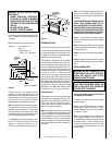
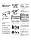
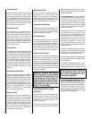
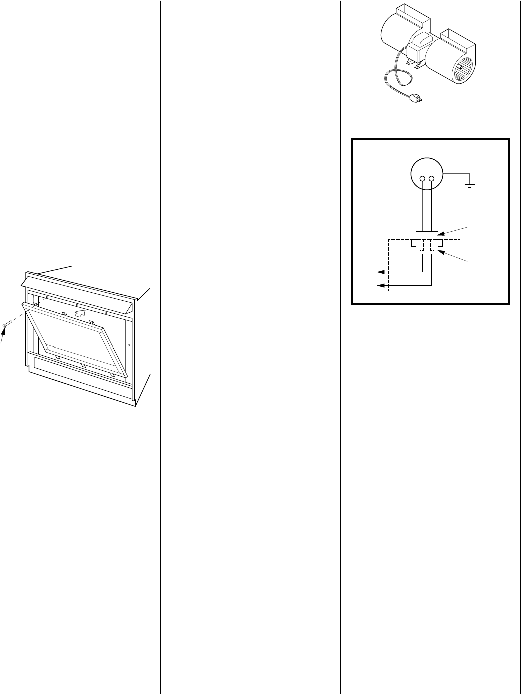
Forced Air Kit
The FAB-1100 assembly (
Figure 26
)provides
a forced air circulation feature for your appli-
ance. This kit mounts directly into the lower
intake chamber, behind the blower shield, with
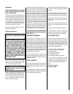
an electrical connection made at the recep-
tacle provided (
Figure 27
). The appliance
must have an independent 120Vac power line
incorporated at the time of installation. Place
the blower against the back wall of the appli-
ance within its chamber behind the blower
shield. The blower shield has to be removed
for blower insertion and replaced before the
installation is complete. The instructions pro-
vided with the blower kit detail all wiring and
operation concerns.
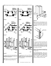
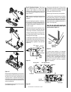
The blower shield located at the back of the
appliance lower control compartment isolates
the blower chamber from the control area in
front. The blower shield is secured in place
with two screws that must be removed and
retained for reuse. Pull the bottom of the
shield forward and bring the top down to
remove the shield horizontally, flat against the
appliance bottom and below the gas controls,
piping, and wiring. The blower may be in-
serted around the right side of the gas controls
after any intervening connecting field installed
gas line has been re-routed or removed. Place
the blower within the chamber, (Refer to the
diagrams provided with the blower Kit) and
reinstall the blower shield. Ensure the blower
wire is routed through the notch in the bottom
edge of the shield.
Access to the blower chamber at the rear of the
lower control compartment in CF-5500 appli-
ances is restricted due to its compact design,
by the interfering tubing of the gas controls
assembly. To provide clearance for the blower,
the spudplate assembly must be lifted up
slightly to allow the blower to be inserted into
its chamber under it. To allow the spudplate to
be lifted, remove the four screws securing it to
the appliance firebox floor. The screws must
be accessed from within the firebox. Refer to
Page 5 and Step 11 for door removal and
replacement, refer to Step 9 for log removal,
handling and placement instructions.
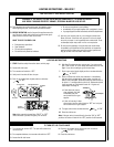
Grounded
to Appliance
Blower Motor
Motor Plug
Receptacle
120V
Appliance Junction Box
Screws
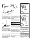
The last ³⁄₈" (10 mm) of the pilot generator
(thermopile) should be engaged with the pilot
flame.
Replace logs if removed for pilot inspection.
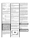
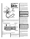
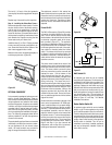
Step 11. Installing the Glass Door Frame –
Retrieve the glass door frame visually. Position
the door frame in front of the firebox opening,
with the joint in the gasket down. Locate the
three (3) tabs at the bottom edge of the door
frame into the three (3) brackets at the base of
the fireplace front opening. Lean the door frame
back towards the fireplace ensuring that the
frame seats evenly as it draws shut.
Install the three (3) ¹⁄₄"-20 x 1" Phillips pan head
screws removed previously and tighten to se-
cure. Ensure that the tab on the bottom of the
door frame engages the door switch.
Make sure the screws are tightened equally to
avoid torquing the door (
Figure 25
).
Figure 25
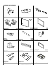
OPTIONAL EQUIPMENT
An incomparable package of options are avail-
able for use with these appliances. These op-
tions can both customize the operation of these
unique appliances and enhance their beauty
and charming appeal. All options are available
in kit form, are easy to install and are packaged
complete with all required parts and instruc-
tions. Some of the option kits need to be fitted
prior to completing the installation of the appli-
ance. The following paragraphs detail the kit
options available for use with the appliances
covered in this manual.
These outstanding optional items can be added
individually or in sets of two or more to custom-
ize your appliance to fit your homes unique
needs. Kit model numbers are provided on
page 14 along with descriptive illustrations.
Figure 27
Wall Switch Kit
An optional wall switch kit can be installed
along with all CF appliances. The kit consists of
a standard UL wall switch with cover plate. This
kit provides for remote (wall) operation of the
appliance. Replace the wall switch and cover
plate of this kit with the components of the RCK
and you can have true remote control of your
direct vent appliance, turning it on and off from
your favorite easy chair. The wall switch kit
should be installed along with the appliance.
Refer to
Figure 15
and Step 7 for detailed
installation instructions.
Rocker Switch Switch Kit
An optional rocker switch kit can be installed
directly on all CF series appliances to provide
for On and Off operation in lieu of a wall switch.
This kit is designed to install in the lower control
compartment out of view and is perfect for use
in high volume areas such as lobbies and model
homes where limited access to the appliance
On/Off switch is desirable. This kit can be
retrofitted to previously installed appliances
and may be temporarily installed in place of
other switch circuitry.
Figure 26