


9
NOTE: DIAGRAMS & ILLUSTRATIONS NOT TO SCALE.
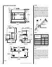
Figure 19
Figure 20
When first lighting the appliance, it will take a
few minutes for the line to purge itself of air.
Once purging is complete, the pilot and burner
will light and operate as indicated in the in-
struction manual.
APPLIANCE OPERATION
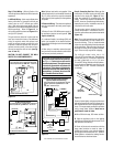
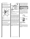
Step 9. Checking the System – With gas line
installed run initial system checkout before
closing up the front of the unit. Follow the pilot
lighting instructions provided in the
Homeowner's Care and Operation Instructions.
For piezo ignitor location see
Figure 20
(milli-
volt appliances only).
Note: Instructions are also found on the pull
out labels attached to the gas control valve.
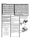
To operate, push the end of the actuator to the
left as shown in
Figure 18
, until it "pops" free
of its "locked" position. Pull the actuator
forward to open the combustion air door, and
push it back to close. To "lock" the combustion
air door closed, ensure the actuator is pushed
all the way back then push the end of the
actuators to the right until the step in the
actuator moves behind the appliance front
face within the slotted opening.
Operate the actuator through several cycles
including the "lock" position. Ensuring proper
operation and freedom of movement. Return
the actuator arm to the locked position.
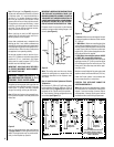
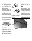
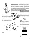
Step 8. Log Placement – This appliance is
equipped with two concrete logs wired and
shipped in place
(see Figure 19 )
. As located
at the factory the log set will require no adjust-
ment before the appliance is placed in service.
Ensure logs are unbroken and located as shown.
To provide increased access to the lower con-
trol compartment, you may chose to remove
the front log. To do so, undo the twists in the
wires securing the log from below to each of the
grate tines. After removal of the log, cut the
wires off closely to log before reinstalling it.
These wires are only required for shipping. To
place the front log, position it, centered, on the
log rack in the cradel area provided.
Piezo Ignitor
Piezo Ignitor
SIT Valve
Honeywell Valve
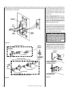
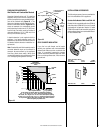
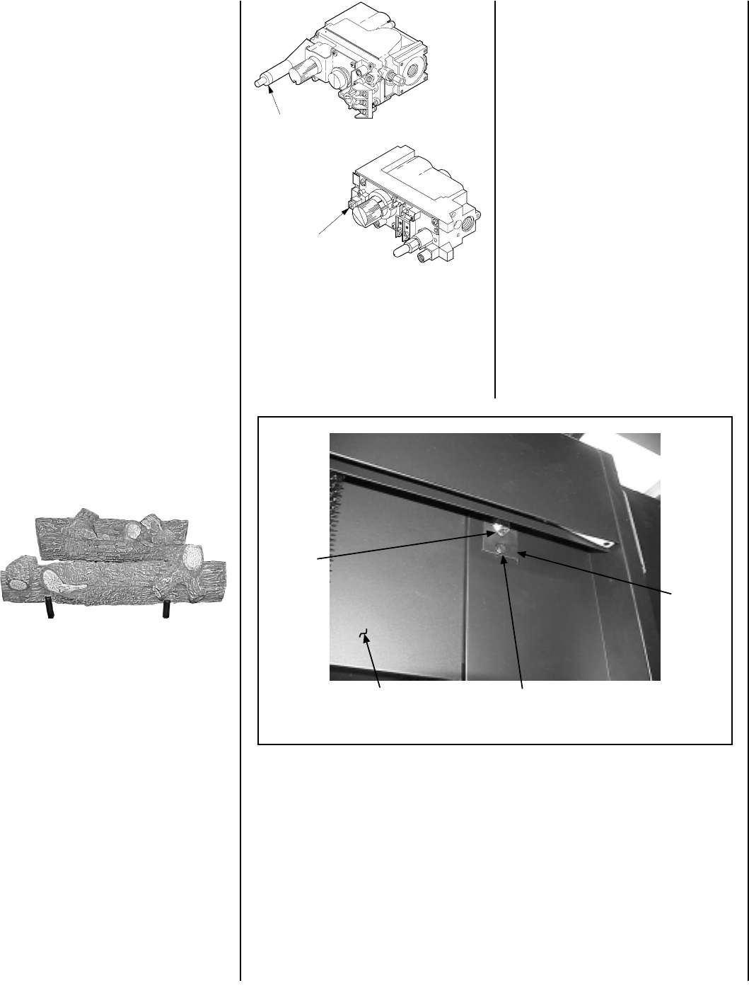
MANUALLY-RESET BLOCKED FLUE SAFETY
SWITCH
This appliance is equipped with a manually-
reset blocked flue safety switch. Refer to
Figure 21
for its location. If during appliance
operation, the flame goes out (independently
of the burner on/off wall switch), it may be due
to the operation of this safety limit switch.
First allow the appliance to cool. Then reset
the safety switch by pushing the red reset
button on the back of the switch.
To access the blocked flue safety switch, re-
move the limit switch bracket, with switch and
low voltage wires attached. Push the red reset
button and then reinstall limit switch bracket.
The appliance should then relight and remain
lit. If this does not occur, turn off the appli-
ance and call a qualified service technician.
Figure 21
Manual
Reset
Limit
Switch
Lintel Extension
Limit
Switch
Bracket
Bracket Screw
Subsequent lightings of the appliance will not
require such purging. Inspect the pilot flame
(remove logs, if necessary, handling care-
fully).