


3
NOTE: DIAGRAMS & ILLUSTRATIONS NOT TO SCALE.
Carbon Monoxide Poisoning: Early signs of
carbon monoxide poisoning are similar to the
flu with headaches, dizziness and/or nausea. If
you have these signs, obtain fresh air immedi-
ately. Turn off the gas supply to the appliance
and have it serviced by a qualified profes-
sional, as it may not be operating correctly.
WARNING: B-VENT APPLIANCES ARE NOT
DESIGNED TO OPERATE IN NEGATIVELY
PRESSURED ENVIRONMENTS (PRESSURE
WITHIN THE HOME IS LESS THAN PRES-
SURES OUTSIDE). SIGNIFICANT NEGA-
TIVELY PRESSURED ENVIRONMENTS
CAUSED BY WEATHER, HOME DESIGN,
OR OTHER DEVICES MAY IMPACT THE
OPERATION OF THESE APPLIANCES.
NEGATIVE PRESSURES MAY RESULT IN
POOR FLAME APPEARANCE, SOOTING,
DAMAGE TO PROPERTY AND/OR SEVERE
PERSONAL INJURY. DO NOT OPERATE
THESE APPLIANCES IN NEGATIVELY PRES-
SURED ENVIRONMENTS.
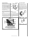
LOCATION
In selecting the location, the aesthetic and
functional use of the appliance are primary
concerns. However, vent system routing to
the exterior and access to the fuel supply are
also important. Due to high temperatures the
appliance should be located out of traffic and
away from furniture and draperies. Consider-
ation should be given to traffic ways, furniture,
draperies, etc., due to elevated surface tem-
peratures. The location should also be free of
electrical, plumbing or other heating/air con-
ditioning ducting.
The appliance should be mounted on a fully
supported base extending the full width and
depth of the unit. The appliance may be located
on or near conventional construction materi-
als. However, if installed on combustible ma-
terials, such as carpeting, vinyl tile, etc., a
metal or wood barrier covering the entire bot-
tom surface must be used.
These appliances may be used for bedroom
installations in the United States and are listed
accordingly. These units may not be installed
in bedrooms in Canada.
CLEARANCES
Minimum clearance to combustibles for the
appliance is as follows: sides and back - 0" (0
mm), floor - 0" (0 mm), adjacent wall - 0" (0
mm), ceiling - 64" (1626 mm).
WARNING: FAILURE TO COMPLY WITH
THE INSTALLATION AND OPERATING IN-
STRUCTIONS PROVIDED IN THIS DOCU-
MENT WILL RESULT IN AN IMPROPERLY
INSTALLED AND OPERATING APPLI-
ANCE, VOIDING ITS WARRANTY. ANY
CHANGE TO THIS APPLIANCE AND/OR
ITS OPERATING CONTROLS IS DANGER-
OUS. IMPROPER INSTALLATION OR USE
OF THIS APPLIANCE CAN CAUSE SERI-
OUS INJURY OR DEATH FORM FIRE,
BURNS, EXPLOSION OR CARBON MON-
OXIDE POISONING.
WARNING: CHILDREN AND ADULTS
SHOULD BE ALERTED TO THE HAZARDS
OF HIGH SURFACE TEMPERATURES. USE
CAUTION AROUND THE APPLIANCE TO
AVOID BURNS OR CLOTHING IGNITION.
YOUNG CHILDREN SHOULD BE CARE-
FULLY SUPERVISED WHEN THEY ARE IN
THE SAME ROOM AS THE APPLIANCE.
WARNING: DO NOT PLACE CLOTHING
OR OTHER FLAMMABLE MATERIALS
ON OR NEAR THIS APPLIANCE.
AVERTISSEMENT: SURVEILLER LES
ENFANTS. GARDER LES VÊTEMENTS,
LES MEUBLES, L'ESSENCE OU AUTRES
LIQUIDES À VAPEUR INFLAMMABLES
LOIN DE L'APPAREIL.
WARNING: THIS APPLIANCE MAY ONLY
BE FITTED WITH DOORS CERTIFIED FOR
USE WITH THE APPLIANCE.
AVERTISSEMENT: POUR UTILISATION
UNIQUEMENT AVEC LES PORTES EN
VERRE CERTIFIÊES AVEC L'APPAREIL.
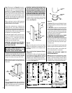
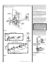
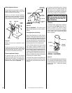
These appliances are equipped with an inte-
gral combustion air door and actuator arm.
Combustion air kits are optional and must be
installed before removing the securing screw
allowing the movement of the combustion air
actuator arm
(see Step 7).
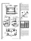
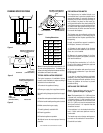
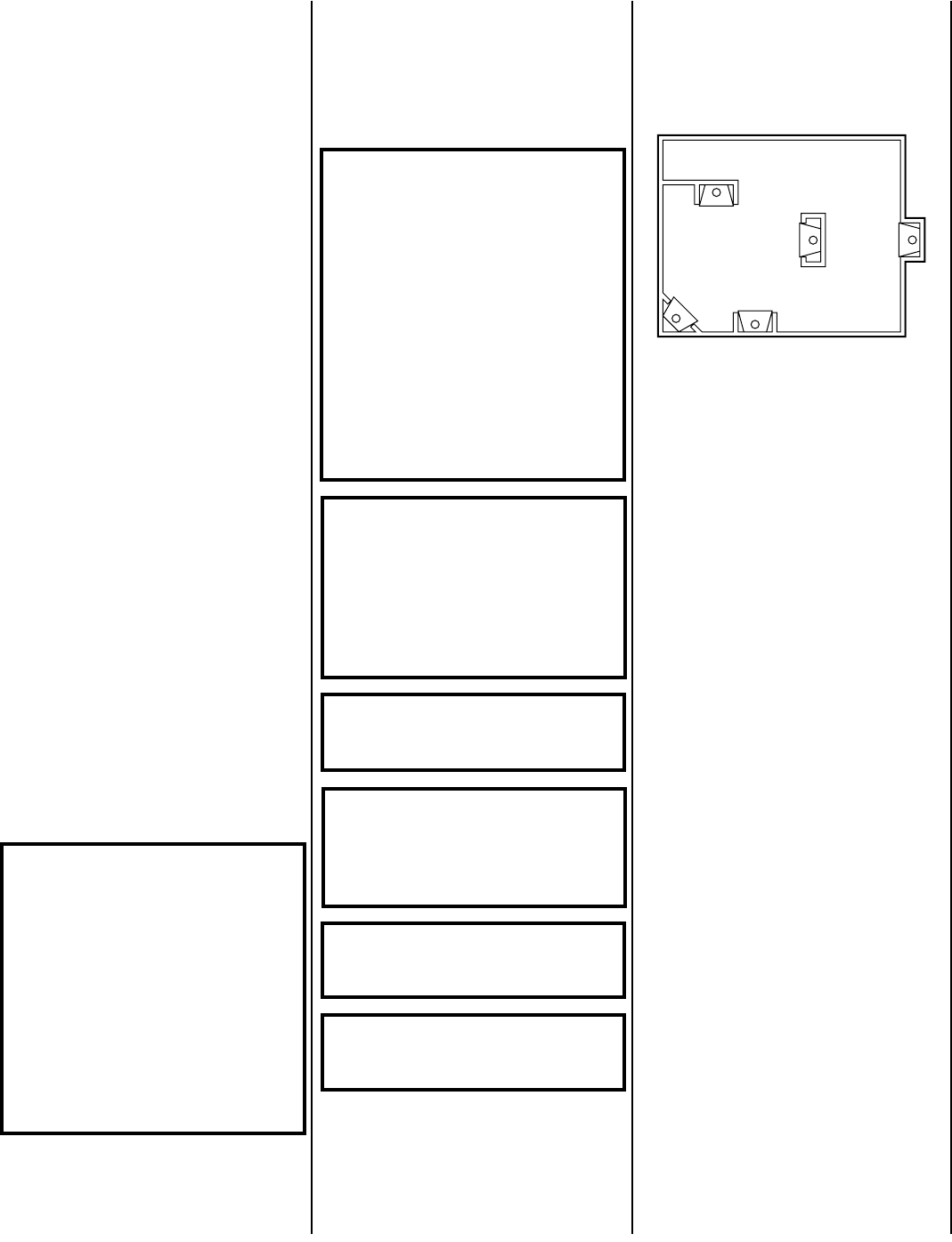
Figure 1
Typical Locations
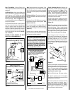
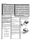
Millivolt appliances may be fitted at time of
manufacture with either a Honeywell millivolt
gas control valve or as SIT millivolt gas control
valve. Both valves have been tested with and
approved for use with these appliances and are
listed accordingly.
Test gage connections are provided on the
front of the millivolt gas control valve (iden-
tified IN for the inlet and OUT for the mani-
fold side). A ¹⁄₈" NPT test gage connection is
provided at the inlet and outlet side of
the electronic gas control valve.
Minimum inlet gas pressure to the appliance is
5.0 inches water column (1.24 kPa) for natural
gas and 11 inches water column (2.74 kPa) for
propane for the purpose of input adjustment.
Maximum inlet gas supply pressure to the
appliance is 10.5 inches water column (2.61
kPa) for natural gas and 13.0 inches water
column (3.23 kPa) for propane.
The appliance must be isolated from the gas
supply piping system (by closing its indi-
vidual manual shut-off valve) during any
pressure testing of the gas supply piping
system at test pressures equal to or less
than ¹⁄₂ psig (3.5 kPa).
The appliance and its individual shut-off
valve must be disconnected from the gas
supply piping system during any pressure
testing of that system at pressures in excess
of ¹⁄₂ psig (3.5 kPa).
These appliances must not be connected to a
chimney or flue serving a separate solid fuel
burning appliance.
Do not place clothing or other materials on or
near this appliance.