


6
NOTE: DIAGRAMS & ILLUSTRATIONS NOT TO SCALE.
Figure 10
Note: Refer to the vent manufacturers installa-
tion instructions for variations of venting tech-
niques. If common venting of several units is
contemplated, it should be discussed with an
architect and the local Building Department.
CAUTION: THIS APPLIANCE CANNOT BE
VENTED HORIZONTALLY.
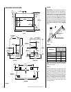
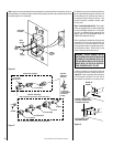
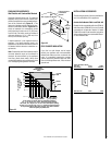
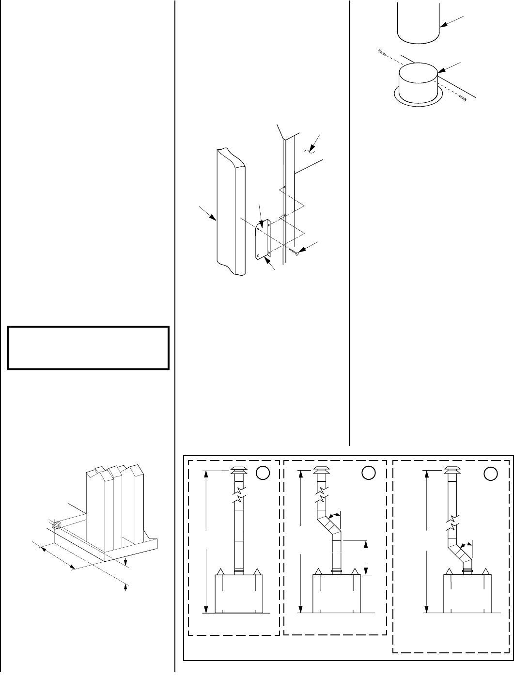
Figure 11
1 - Vertical - Minimum overall height of the vent
system and appliance without an offset must be
12' (3.66 m)
2 - With Offset - Minimum overall height of the
vent system and appliance must be 15' (4.57 m)
when an offset up to 60 degrees from the vertical
is used. There must be a minimum vertical vent
height of 2 ft. (0.6 m) above the appliance collar
before the offset can be applied.
3 - With Offset, when using the optional, 36GEP
or 36GEP-BB, non-operable glass doors -
Minimum overall height of the vent system and
appliance must be 12' (3.66 m) when an offset
up to 60 degrees from the vertical is used. The
lower part of the offset may start at the appli-
ance flue collar.
Maximum overall height of the vent system and
appliance should not exceed 40 feet (12.19 m).
Install the B-vent system in accordance with
the vent manufacturer's instructions.
IMPORTANT: UNDER NO CIRCUMSTANCES CAN
THE FIREPLACE TOP SPACERS (
FIGURE 2
) BE
REMOVED OR MODIFIED, NOR MAY YOU NOTCH
THE HEADER TO FIT AROUND OR BE INSTALLED
LOWER THAN THE SPACERS. THE HEADER MAY
BE IN DIRECT CONTACT WITH THE TOP SPAC-
ERS BUT MAY NOT BE SUPPORTED BY THEM.
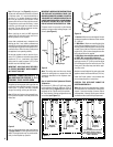
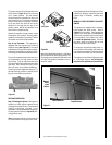
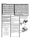
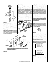
Fireplace should be secured to side framing
members using provided nailing flanges. Use
8d nails
(see Figure 9 )
.
Figure 8
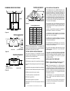
Step 2. Route gas line
(Figure 8)
using tech-
niques and materials prescribed by local and/
or national codes. It is recommended that a
gas line of ¹⁄₂" or greater diameter be used to
allow full gas volume to the fireplace. Undue
pressure loss will occur if the pipe is too small.
The appliance, as set up at the factory, is best
suited for use with a gas line routed from the
right side. The gas line may however be alter-
nately routed from the left side.
When rigid pipe is used, an ANSI approved
manual shut-off valve and union must be in-
stalled upstream of the fireplace.
Ensure that a sediment trap is installed in the
existing gas line, if not, install a sediment trap
upstream to prevent moisture and contaminants
from passing through trap to the appliance con-
trols and burners. Failure to do so could prevent
the appliance from operating reliably.
An external regulator must be used on all pro-
pane (L.P.G.) heaters to reduce the supply tank
pressure to 13" w.c. (maximum). Any copper
tubing used to supply propane (L.P.G.) from
the tank must be internally tinned.
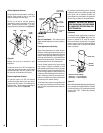
IMPORTANT: HOLD GAS VALVE SECURELY
TO PREVENT MOVEMENT WHEN CONNECT-
ING TO INLET GAS LINE
WARNING: CONNECTING DIRECTLY TO
AN UNREGULATED PROPANE (L.P.G.)
TANK MAY CAUSE AN EXPLOSION.
Figure 9
All appliances are equipped with a gas flex line
and shutoff valve attached directly to the gas
control valve. To quickly and easily complete
the gas line routing, use the gas flex line kit.
Step 3. Slide the fireplace into prepared fram-
ing or position fireplace in its final position and
frame later.
Note: The nailing tabs and the area directly
behind the nailing tabs are exempt from the
clearances described on the fireplace clear-
ance label.
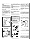
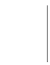
Step 4. Install the Vent System and Exterior
Termination -
A - Connect a 4" (102 mm) Type B vent system
to the appliance flue collar with two (2) No. 8
sheet metal screws
(Figure 10 )
and install the
remainder of the Type B vent to the outside.
B - The following venting configurations may
be installed
(see Figure 11):
*This Vent Configuration Allowable
Only WithThe Following Optional
Non-Operable Glass Doors installed:
36GEP or 36GEP-BB
Refer to fireplace drawings and specifications
on
pages 4 and 5
for framing dimensions and
details. Framing header may be positioned di-
rectly on the fireplace top spacers.
RIGHT
SIDE
5 ³⁄₄"
(146 mm)
2 ¹⁄₄"
(57 mm)
4” Type B
Vent
Flue Outlet
Collar
15 ft.
Minimum
With Any
Offset
2 ft.
Minimum
To Offset
12 ft.
Minimum
60*
degrees
Maximum
Back View
Of Appliance
Back View
Of Appliance
60
degrees
Maximum
12 ft.
Minimum
Back View
Of Appliance
1
2
3
8d Nail
Framing
Appliance
Louver
Nailing Flange