


7
NOTE: DIAGRAMS & ILLUSTRATIONS NOT TO SCALE.
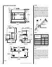
Figure 13 Figure 14
Figure 12
Figure 15
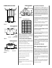
Secure all joints tightly using appropriate tools
and sealing compounds (ensure propane resis-
tant compounds are used in propane applica-
tions). Turn on gas supply and test for gas leaks
using a soapy water solution. Never use an
open flame to check for leaks.
A. Mix a 50% dish soap, 50% water solution.
B. Light the appliance (refer to the lighting
instructions provided in the Homeowner's Care
and Operation Instructions).
C. Brush all joints and connections with the
soapy water solution to check for leaks. If
bubbles are formed, or gas odor is detected,
turn the gas control knob to the “OFF” position.
Either tighten or refasten the leaking connec-
tion and retest as described above.
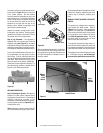
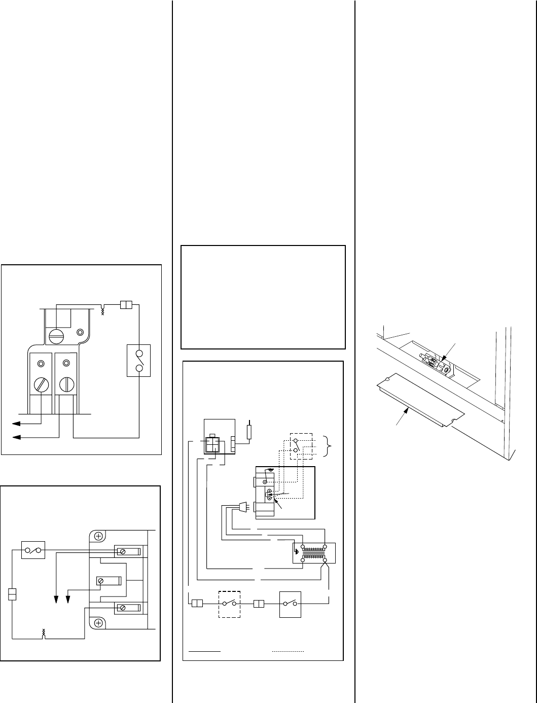
The gas control valve is located in the lower
control compartment. To access the valve re-
move the removable access panel and set aside
(Figure 15 ).
Note: To provide increased access to the lower
control compartment, you may choose to re-
move the front log. To do so, undo the twists
in the wires securing the log from below to each
of the grate tines. After removal of the log cut
the wires off closely to the log before reinstall-
ing it. These are only required for shipping.
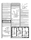
The millivolt control valve has a ³⁄₈"
(10 mm) NPT thread inlet port. The electronic
control valve has a ¹⁄₂" (13 mm) NPT thread inlet
port and is fitted with a ¹⁄₂" x ³⁄₈" (13 mm x
10 mm) NPT fitting. Both the millivolt and elec-
tronic models are fitted with a gas flex line and
shutoff valve, ³⁄₈" NPT. Plan the connections
accordingly.
Note: Optional wall switch not supplied. If the
optional wall switch is not installed, the ends of
the 15' (4.5m) coiled wire must be connected
with a wire nut (not supplied) for the appliance
to operate.
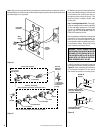
B. Electronic Wiring – The electronic appliance
must be connected to the main power supply.
To install:
1. Route a 3-wire 120V 60Hz power supply to
the appliance junction box and ground.
(See
Figures 14 and 16 ).
2. Locate and install a low voltage (24V) wall
switch (not supplied) in the desired location.
Connect the low voltage wire to this switch
(see
Figure 14 )
.
3. After wiring is complete, replace the appli-
ance junction box cover and secure with the hex
head screws previously removed.
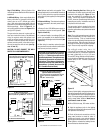
Step 5. Field Wiring – Refer to Section A for
millivolt appliances and Section B for electronic
appliances.
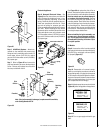
A. Millivolt Wiring – Units may be fitted at the
factory with either a Honeywell millivolt gas
control valve or an SIT millivolt gas control
valve. Both valves have been tested with and
approved for use with these appliances and are
listed accordingly. Refer to
Figure 12
for
wiring of Honeywell systems and
Figure 13
for
wiring of SIT systems.
The gas valve has been set in place and has
been pre-wired at the factory. No additional
wiring is required unless the optional wall
switch or optional remote control kit is to be
installed. Locate the optional wall switch or
optional remote control in the desired loca-
tion and connect the millivolt wire
(see Fig-
ures 12 and 13 )
.
CAUTION: DO NOT CONNECT THE WALL
SWITCH TO A 120V POWER SUPPLY.
IMPORTANT: Ground lead must be connected
to the green screw located on the outlet box.
See
Figure 14
. Failure to do so will result in
a potential safety hazard. The appliance must
be electrically grounded in accordance with
local codes or, in the absence of local codes,
the National Electrical Code, ANSI/NFPA 70-
(latest edition). (In Canada, the current CSA
C22-1 Canadian Electrical Code.)
Step 6. Connecting Gas Line – Make gas line
connections. All codes require a shut-off valve
mounted in the supply line.
Figure 17
illus-
trates two methods for connecting the gas
supply. The flex-line method is acceptable in
the U.S., however, Canadian requirements vary
depending on locality. Installation must be in
compliance with local codes.
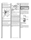
Thermopile
TH
TP
TH
TP
Honeywell Millivolt Wiring Diagram
If any of the original wire as supplied must be replaced,
it must be replaced with Type AWM 105°C – 18 GA. wire.
TH
TPTH
TP
* For Wall Switch Attachment Only.
*
Limit
Switch
BK
WHT
BK
BK
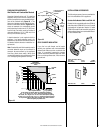
SIT Millivolt Wiring Diagram
* For Wall Switch Attachment Only.
If any of the original wire as supplied must be replaced, it
must be replaced with Type AWM 105°C – 18 GA. wire.
Thermopile
TH
TP
TH
TP
Limit Switch
BK
BK
BK
WHT
*
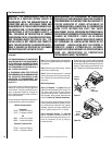
1. If any of the original wire as supplied must be replaced,
1. it must be replaced with Type AWM 105°C – 18 GA.
wire.
2. 120V, 60Hz – Less than 3 amps.
BK
Junction Box
Transf.
120 V.
24 V
Factory Wired
Field Wired
BL
Electronic Wiring Diagram (Honeywell)
(Optional ON/OFF Switch Wiring)
R
BK
BL
To Opposite Side
G
W
OPT. ACCESSORY
SWITCH
120
VAC.
BK
LIMIT
SWITCH
W
Gas Valve
B
OPTIONAL
ON/OFF SWITCH
OR
WALL SWITCH
R
IGNITER
CONTROL
PILOT
ASSEMBLY
Break
Off Tab
BK
WHT
BK
BK
G
G
Gas Controls
on Valve
SIT Valve Shown
Removable
Access Panel