


356214-XIM-A-0108
42 Johnson Controls Unitary Products
FLASH CODES
The UCB will initiate a flash code associated with
errors within the system. Refer to UNIT CONTROL
BOARD FLASH CODES Table 24.
RESETS
Remove the call for heating by lowering the thermostat
setting lower than the conditioned space temperature.
This resets any flash codes.
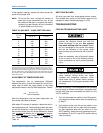
HEAT ANTICIPATOR SETPOINTS
It is important that the anticipator setpoint be correct.
Too high of a setting will result in longer heat cycles
and a greater temperature swing in the conditioned
space. Reducing the value below the correct setpoint
will give shorter "ON" cycles and may result in the low-
ering of the temperature within the conditioned space.
START-UP (COOLING)
PRESTART CHECK LIST
After installation has been completed:
1. Check the electrical supply voltage being supplied.
Be sure that it is the same as listed on the unit
nameplate.
2. Set the room thermostat to the off position.
3. Turn unit electrical power on.
4. Set the room thermostat fan switch to on.
5. Check indoor blower rotation.
• If blower rotation is in the wrong direction. Refer to
Phasing Section in general information section.
• Check blower drive belt tension.
6. Check the unit supply air (CFM). See "CHECKING
SUPPLY AIR CFM" on page 34.
7. Measure evaporator fan motor's amp draw.
8. Set the room thermostat fan switch to off.
9. Turn unit electrical power off.
OPERATING INSTRUCTIONS
1. Turn unit electrical power on.
2. Set the room thermostat setting to lower than the
room temperature.
3. First stage compressors will energize after the
built-in time delay (five minutes).
4. The second stage of the thermostat will energize
second stage compressor if needed.
POST START CHECK LIST
1. Verify proper system pressures for both circuits.
2. Measure the temperature drop across the evapora-
tor coil.
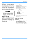
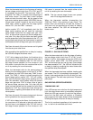
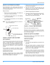
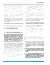
FIGURE 20 - GAS VALVE AND CONTROLS
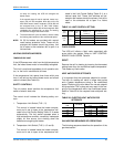
TABLE 22: GAS HEAT ANTICIPATOR SETPOINTS
Gas Valve
Anticipator Setpoint
1st Stage 2nd Stage
Honeywell VR8440
0.30 amp 0.11 amp
White-Rodgers 36C68
IG N . C O N T R O L # 1
IG N . C O N T R O L # 2
IG N IT O R # 1
G V 1
G A S
V A L V E
G V 2
G A S
V A L V E
IG N IT O R # 2
S E N S O R # 2
S E N S O R # 1
R O L L O U T S W
.
B U R N E R C O M P A R T M E N T