


356214-XIM-A-0108
14 Johnson Controls Unitary Products
OPTIONAL GAS HEAT
These gas-fired heaters have aluminized-steel or
optional stainless steel, tubular heat exchangers with
spark ignition with proven pilot.
All gas heaters are shipped from the factory equipped
for natural gas use, but can be field converted to L.P./
Propane with Kit Model # 1NP0418. See Gas Heat
Application Data Table.
GAS PIPING
Proper sizing of gas piping depends on the cubic feet
per hour of gas flow required, specific gravity of the gas
and the length of run. "National Fuel Gas Code" Z223.1
(in U.S.A.) or the current Gas Installation Codes CSA-
B149.1 (in Canada) should be followed in all cases
unless superseded by local codes or gas utility require-
ments. Refer to the Pipe Sizing Table 5.
The heating value of the gas may differ with locality.
The value should be checked with the local gas utility.
NOTE: There may be a local gas utility requirement
specifying a minimum diameter for gas piping.
All units require a one-inch pipe connection at
the entrance fitting.
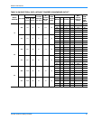
Maximum capacity of pipe in cubic feet of gas per hour. (Based upon
a pressure drop of 0.3 inch water column and 0.6 specific gravity
gas).
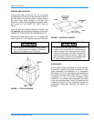
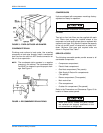
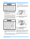
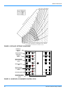
GAS CONNECTION
The gas supply line can be routed through the knock-
outs located on the front of the unit or through the
opening provided in the unit's base. Refer to the
Dimensions and Clearances Figure 13 to locate these
access openings. Typical supply piping arrangements
are shown in the figures on page 15. All shaded items
are field-supplied.
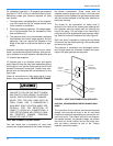
If gas supply line is routed through the unit's base
ensure that the burner assembly can be removed for
maintenance without disturbing the supply line. The
supply piping and fittings must lie below the bottom gas
manifold to avoid interference with the burner assem-
bly.
Two grommets are shipped in the blower compartment
(in parts bag taped to the blower housing) of every unit
with gas heat and should be used in the knockouts
when the gas piping penetrates the front of the unit.
After the gas supply piping has been installed, the bot-
tom opening in the unit should be sealed to prevent
water from leaking into the building.
Gas piping recommendations
:
1. A drip leg and a ground joint union must be
installed in the gas piping.
2. When required by local codes, a manual shut-off
valve may have to be installed outside of the unit.
3. Use wrought iron or steel pipe for all gas lines. Pipe
compound should be applied sparingly to male
threads only.
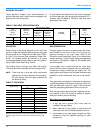
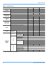
TABLE 4: GAS HEAT APPLICATION DATA
0 To
2,000 Feet
Above
Sea Level
2,000 To
4,500 Feet
Above
Sea Level
Output Capacity (Mbh)
Available
on Models
Gas
Rate
(Ft./Hr.)
Temp.
Rise ºF
At
Full Input
0 To
2,000 Feet
Above
Sea Level
2,000 To
4,500 Feet
Above
Sea Level
Max. Min. Max. Min. Max. Max. Min. Max.
300 150 270 135 240 213 15, 20 & 25 Ton 279 20 50
350 175 320 160 280 241 25 Ton 326 30 60
TABLE 5: PIPE SIZING
Length in Feet
Nominal Iron Pipe Size
1 in. 1-1/4 in.
10 520 1,050
20 350 730
30 285 590
40 245 500
50 215 440
60 195 400
70 180 370
80 170 350
90 160 320
100 150 305