


356214-XIM-A-0108
16 Johnson Controls Unitary Products
For satisfactory operation, L.P./propane gas pressure
must be 10.0 I.W.C. at the unit manifold under full load.
Maintaining proper gas pressure depends on three
main factors:
1. The vaporization rate depends on (a) the tempera-
ture of the liquid and (b) the "wetted surface" area
of the container or containers.
2. The proper pressure regulation. (Two-stage regula-
tion is recommended from the standpoint of both
cost and efficiency.)
3. The pressure drop in the lines between regulators
and between the second stage regulator and the
appliance. Pipe size required will depend on the
length of the pipe run and the total load of all appli-
ances.
Complete information regarding tank sizing for vapor-
ization, recommended regulator settings, and pipe siz-
ing is available from most regulator manufacturers and
L.P./propane gas suppliers.
L.P./propane gas is an excellent solvent and special
pipe compound must be used when assembling piping
for this gas as it will quickly dissolve white lead or most
standard commercial compounds. Shellac base com-
pounds such as Rectorseal #5 are satisfactory for this
type of gas.
Check all connections for leaks when piping is com-
pleted, using a soap solution. NEVER USE A FLAME.
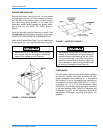
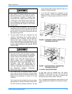
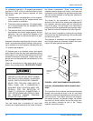
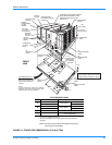
VENT AND COMBUSTION AIR HOODS
Two vent hoods and a combustion air hood (with
screens) are shipped attached to the blower housing in
the blower compartment. These hoods must be
installed to assure proper unit function. All hoods must
be fastened to the outside of the gas heat access panel
with the screws provided in the bag also attached to
the blower housing.
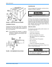
The screen for the combustion air intake hood is
secured to the inside of the access panel opening with
four fasteners and the screws used for mounting the
hood to the panel. The top flange of this hood slips in
under the top of the access panel opening when install-
ing. Refer to Vent and Combustion Air Hood Figure 8.
Each vent hood is installed by inserting the top flange
of the hood into the slotted opening in the access panel
and securing in place.
The products of combustion are discharged horizon-
tally through these two screened, hooded vent open-
ings on the upper gas heat access panel.
OPTIONAL ECONOMIZER/MOTORIZED DAMPER RAIN
HOOD
The instruction for the optional economizer/motorized
damper rain hood can be found in the kit. Use these
instructions when field assembling an economizer rain
hood onto a unit. The outdoor and return air dampers,
the damper actuator, the damper linkage, the outdoor
and return air divider baffles, and all the control sen-
sors are factory mounted as part of the "Factory
installed" economizer option.
FIRE OR EXPLOSION HAZARD
FAILURE TO FOLLOW THE SAFETY WARN-
ING EXACTLY COULD RESULT IN SERIOUS
INJURY, DEATH OR PROPERTY DAMAGE.
NEVER TEST FOR GAS LEAKS WITH AN
OPEN FLAME. USE A COMMERICALLY
AVAILABLE SOAP SOLUTION MADE SPE-
CIFICALLY FOR THE DETECTION OF
LEAKS TO CHECK ALL CONNECTIONS. A
FIRE OR EXPLOSION MAY RESULT CAUS-
ING PROPERTY DAMAGE, PERSONAL
INJURY OR LOSS OF LIFE.
FIGURE 8 - VENT AND COMBUSTION AIR HOOD
VENT AIR
OUTLET
HOODS
SLOTTED
OPENINGS IN
ACCESS PANEL
COMBUSTION
A
IR INTAKE
HOOD
GAS HEAT
ACCESS
PANELS