


356214-XIM-A-0108
Johnson Controls Unitary Products 13
THERMOSTAT
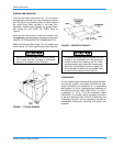
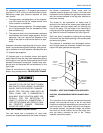
The room thermostat should be located on an inside
wall approximately 56 inches above the floor where it
will not be subject to drafts, sun exposure or heat from
electrical fixtures or appliances. Follow manufacturer's
instructions enclosed with thermostat for general instal-
lation procedure. A minimum of seven color-coded
insulated wires (#18 AWG) should be used to connect
thermostat to unit.
POWER AND CONTROL WIRING
Field wiring to the unit must conform to provisions of
the National Electrical Code, ANSI / NFPA No. 70 (in
U.S.A.), current Canadian Electrical Code C22.1 (in
Canada) and/or local ordinances. The unit must be
electrically grounded in accordance with NEC and CEC
(as specified above) and/or local codes. Voltage toler-
ances, which must be maintained at the compressor
terminals, during starting and running conditions, are
indicated on the unit Rating Plate and the Unit Applica-
tion Data table.
The internal wiring harness furnished with this unit is
an integral part of a CSA design certified unit. Field
alteration to comply with electrical codes should not be
required.
A fused disconnect switch should be field provided for
the unit. The switch must be separate from all other cir-
cuits. Wire entry at knockout openings require conduit
fittings to comply with NEC (in U.S.A.), CEC (in Can-
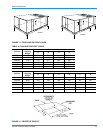
ada) and/or local codes. Refer to the Dimensions and
Clearances Figure 13 for installation location. If any of
the wire supplied with the unit must be replaced,
replacement wire must be of the type shown on the wir-
ing diagram and the same minimum gauge as the
replaced wire.
Electrical line must be sized properly to carry the load.
Use copper conductors only. Each unit must be wired
with a separate branch circuit fed directly from the
meter panel and properly fused.
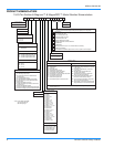
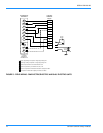
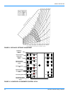
Refer to the Typical Field Wiring Figure 5 and to the
appropriate unit wiring diagram for control circuit and
power wiring information.
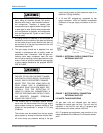
OPTIONAL ELECTRIC HEAT
The factory-installed heaters are wired for single point
power supply. Power supply need only be brought into
the single point terminal block and thermostat wiring to
the low voltage terminal strip located in the upper por-
tion of the unit control box.
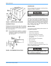
These CSA approved heaters are located within the
central compartment of the unit with the heater ele-
ments extending into the supply air chamber. Refer to
Figure 13 for access panel location.
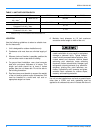
Fuses are supplied, where required, by the factory.
Some KW sizes require fuses and others do not. Refer
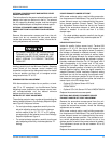
to Table 3 for minimum CFM limitations and to Tables 8
and 9 for electrical data.
When connecting electrical power and control
wiring to the unit, waterproof type connectors
MUST BE USED so that water or moisture
cannot be drawn into the unit during normal
operation. The above waterproofing conditions
will also apply when installing a field-supplied
disconnect switch.
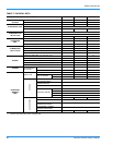
TABLE 2: CONTROL WIRE SIZES
Wire Size
Maximum Length
1
1.
From the unit to the thermostat and back to the unit.
18 AWG 150 Feet
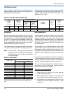
TABLE 3: ELECTRIC HEAT APPLICATION DATA
NOMINAL
HEATER SIZE
(KW)
VOLTAGE
3-PHASE,
50 HZ
MINIMUM CFM UNIT SIZE
15 TON 20 TON 25 TON
18 380/415 4500 6000 7500
36 380/415 4500 6000 7500
54 380/415 5000 6000 7500
72 380/415 5000 6000 7500