STT40 / STT70
Functional description 6-18
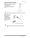
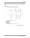
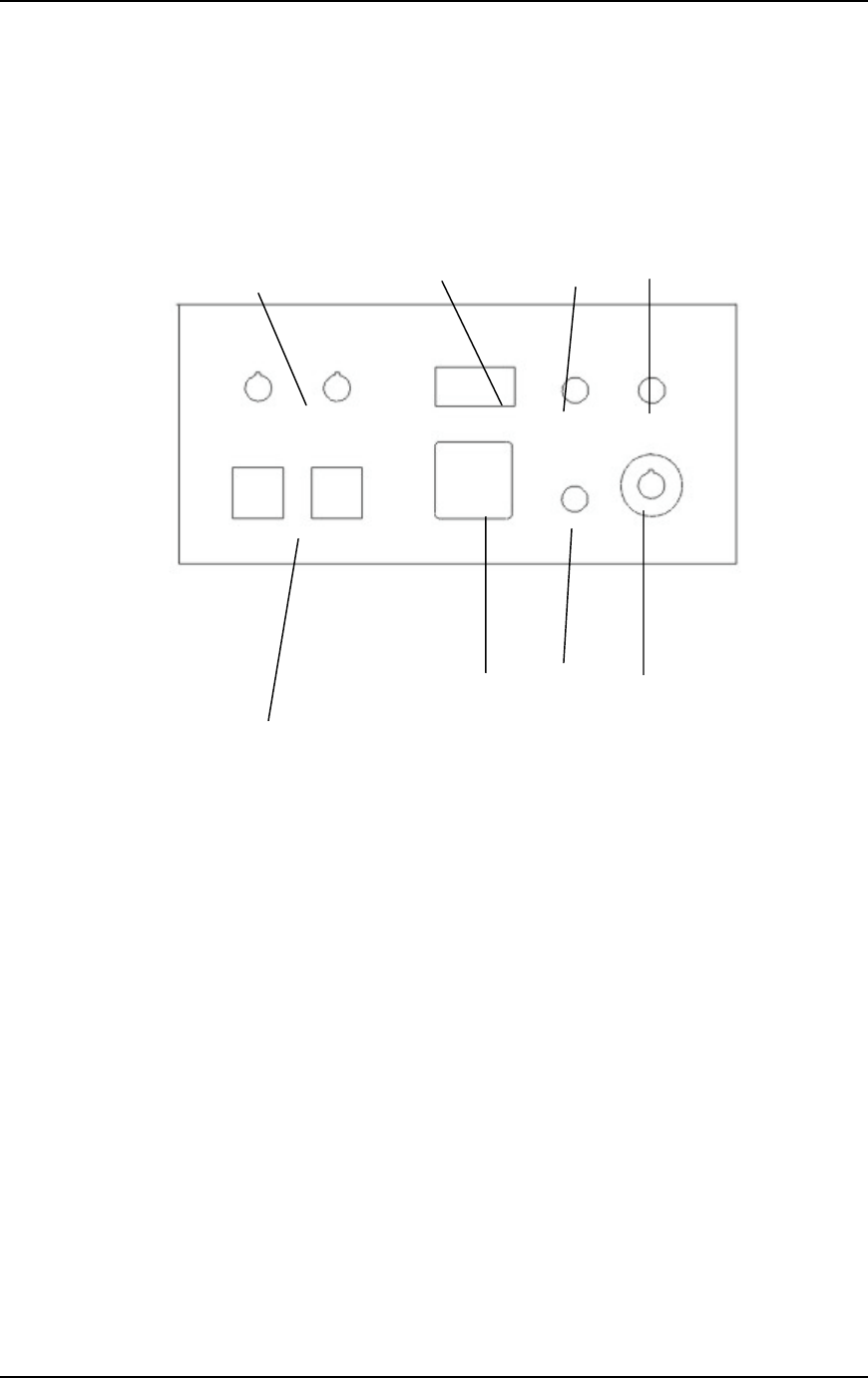
1 = “hopper” release switch STT1, STT2 (STT2 only STT70)
2 = dew point display (op tional)
3 = “power” signal lamp
4 = “trouble” signal lamp
5 = main power switch
6 = “Timer” release switch
7 = timer clock (op tional)
8 = temperature controller “drying hopper” STT1, STT2 (STT2 only STT70)
Figure 10: Operating unit
A digital display of the current dew point temperature can be supplied as additional equipment.
An optional timer clock can also be supplied which switches the dryer on or off at preselected
times.
) Read the timer clock operating manual.
2
1
3
6
5
4
8
7


