


Dehumidifying Dryers Chapter 4: Operation 35 of 59
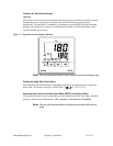
3. Once the control power is on and no fault conditions exist, turning the OFF-ON-
START switch to the START position will start the dryer as follows:
a. The process heater is turned on and controlled by the E5CN controller.
b. The process/regen blower is started.
c. The regen heater is turned on and the regeneration timing sequence is
initiated. The regen heater is controlled by the E5C2 controller. For default
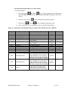
timing settings for regeneration, see the table below.
Model Heating Cooling
15 cfm
30 cfm
35 30
60 cfm
35 30
Note: In a humid environment, you may change the setting to 40 / 25 for
better results.
4. If either the left or right bed safety temperature switch opens, a regen heater fault is
generated. “HIGH TEMP” is displayed on the relay screen. The alarm light is
activated. The process heater, regen heater, and process/regen blower are turned off.
Turn the Off-On-Start switch to the START position to deactivate the alarm light and
restart the dryer. If the switch is still open, the dryer will not restart.
5. If the OMRON controller faults, the optional redundant high temperature safety
device opens, or the process heater safety switch opens, a heater fault is generated.
“HIGH TEMP” is displayed on the relay screen. The alarm light is activated. The
process heater, regen heater, and process/regen blower are turned off.
Turn the OFF-ON-START switch to the START position to deactivate the alarm
light and restart the dryer. If the fault condition still exists, the dryer will not restart.
6. If the process blower overload trips, a process blower fault is generated. “PROC
BLWR” is displayed on the relay screen. The alarm light is activated. The process
heater, regen heater, and process/regen blower are turned off.
Reset the motor overload and turn the Off-On-Start switch to the START position to
deactivate the alarm light and restart the dryer.
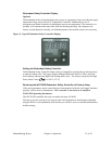
7. The valve position limit switch enables the right bed heater and provides an input
signal to the programmable relay when actuated by the cam lobe. When the cam lobe
position is high, the right bed is activated. When the cam lobe position is low, the
left bed is activated. Each heater is ON-OFF controlled by the OMRON E5C2
controller.
8. Upon completion of the HEAT portion of the regeneration sequence, the regen
heaters are disabled by the programmable relay and the COOL time begins.
9. Once the Cool time has expired, the valve motor is turned on until the cam switch
makes a transition. Upon making a transition, the timing sequence is restarted for the
new bed.
10. When no fault conditions exist, the display reads “SYSTEM NORMAL”.