Large Dehumidifying Dryers Controls 35
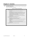
4-2 Identifying Control Panel Components for the AP-1 Optional
Controller
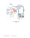
Disconnect Switch
The Disconnect Switch is located in the front upper right hand corner of the control
enclosure. It allows the user to disconnect power to the dryer for emergency shutdown,
service or long periods of inactivity.
Control Power Switch
The Control Power Switch is located on the front of the control enclosure below the touch
screen. The switch energizes the control circuit (PLC, touch screen, relays, etc.) within the
control enclosure.
Touch Screen
The Touch Screen is located in the center of the control enclosure. Once the disconnect is
on and the control circuit is energized, the machine can be started and parameters can be
adjusted through the touch screen.
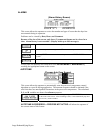
Alarm Horn & Light
The Alarm Horn and the Alarm Light are located on the top of the enclosure. These
devices give an audible and visual indication that there is a malfunction with the system.
4-3 Process Air Temperature and Conveying Process Controller
AEC dryers equipped with the “AP-1” control package use a PLC with a touch screen
interface to control the operation of the dryer system. This section of the manual will address
those parameters that allow the user to optimize the drying/conveying system for specific
applications.
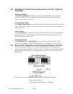
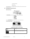
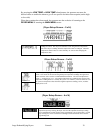
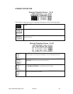
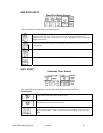
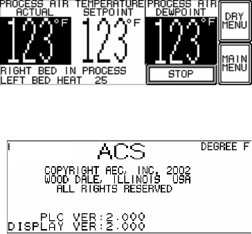
(Dryer Status Screen)
(Startup Screen)
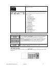
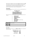
The screen shown above provides the operator with the following information:
• Dryer Model Number
• Temperature units (In Celsius or Fahrenheit)


