


Large Dehumidifying Dryers Mechanical Installation 27
; Make sure all electrical connections are tight.
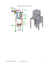
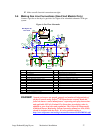
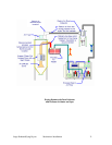
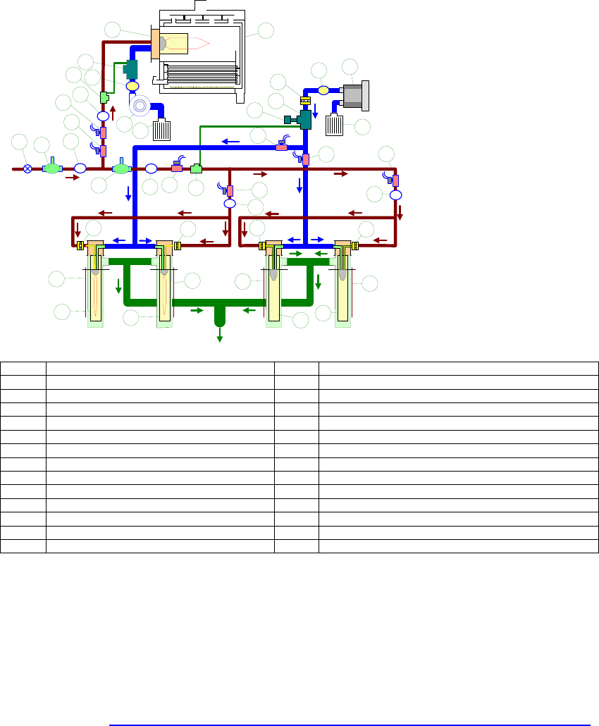
3-4 Making Gas Line Connections (Gas-Fired Models Only)
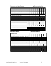
Connect a gas line to the dryer’s gas inlet. See Figure 6 for a detailed schematic of the gas
system.
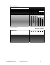
Figure 6: Gas Flow Schematic
PS
Fume
Exhaust
PS
PS
C
B
1
2
3
4
4
6
7
8
9
10
11
12
13
14
3
16
17
16
PS
3
20
21
22
21
21
21
20
20
20
22
22
22
16
3
23
24
25
PS
PS
P
S
5
15
15
18
19
Gas Dryers Air
Fuel Train
Item Description Item Description
1 Manual gas shut off valve 14 Regeneration gas regulator
2 Gas regulator 15 Regeneration air solenoid valve
3 Gas pressure switch 16 Regeneration gas solenoid valve
4 Process gas solenoid valve 17 Regeneration gas proportionator
5 Manual adjustable butterfly valve 18 Regeneration butterfly orifice valve
6 Process gas proportionator 19 Regeneration air actuator
7 Process air actuator 20 Adjustable gas orifice
8 Air pressure switch 21 Regeneration thermocouple
9 Process ratiomatic burner 22 Regeneration SER burner
10 Process gas heat exchanger 23 Regeneration & combustion air filter
11 Gas pressure switch 24 Combustion air blower
12 Process combustion air blower 25 Air pressure switch
13 Process combustion air filter
DANGER! Natural gas burners are started, stopped, and monitored independently of
the dryer controls using Eclipse
TM
Bi-Flame burner controls. Read and
follow the burner control manufacturer’s operating and safety instructions
and applicable NFPA© (National Fire Protection Association) codes in
addition to your local rules and regulations. The Eclipse Bi-Flame model
6500 Dual Burner Monitoring System (instruction manual no. 826, 05/03)
should be included with the dryer. It is also available online at
http://www.eclipsenet.com/catalog/contents/Documents/08/826IM0503s.pdf