


26
When checking the Temperature-Pressure Relief Valve operation,
make sure that (1) no one is in front of or around the outlet of the
Temperature-Pressure Relief Valve discharge line, and (2) that
the water discharge will not cause any property damage, as the
water may be extremely hot. Use care when operating valve as
the valve may be hot.
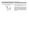
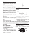
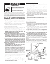
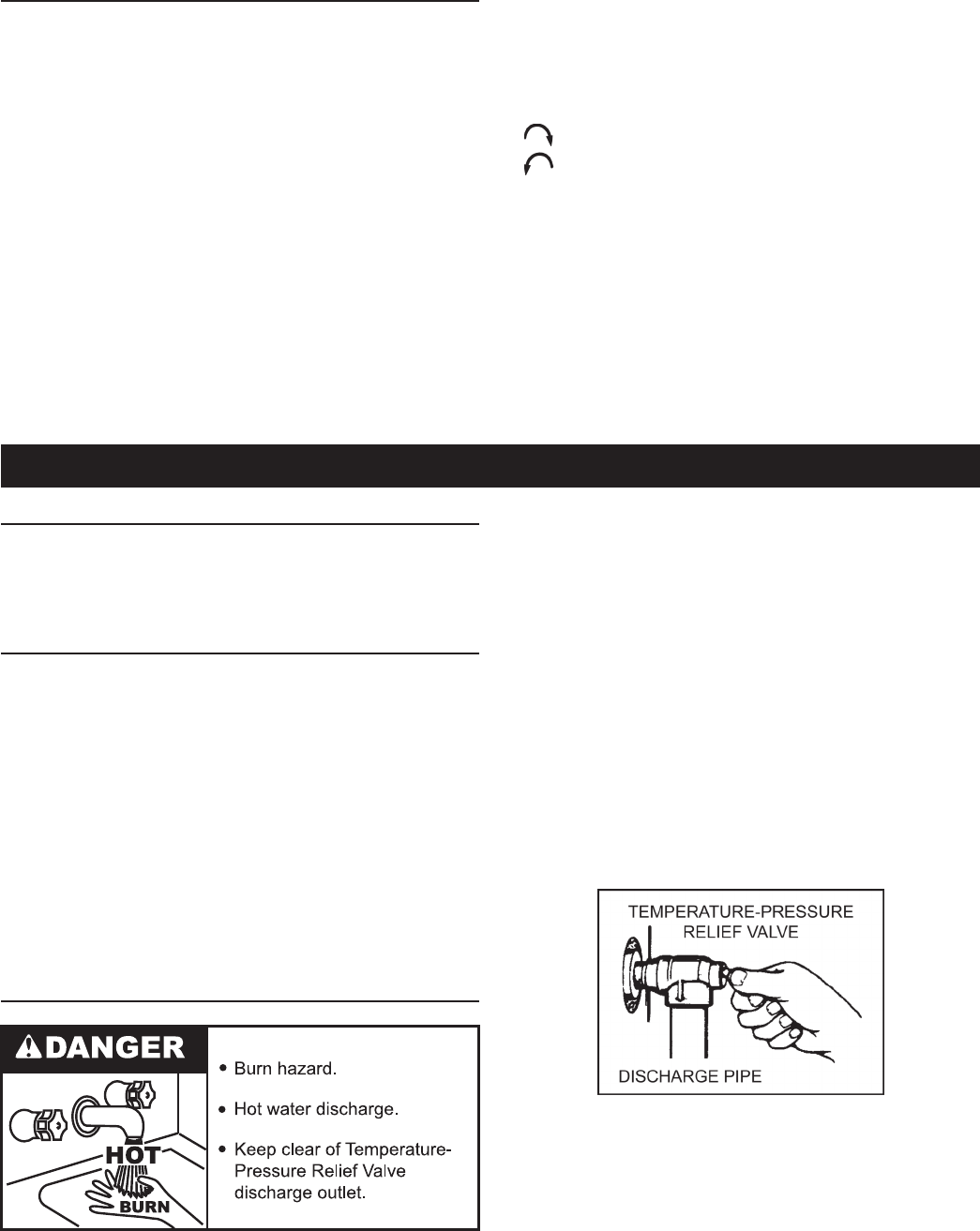
To check the relief valve, lift the lever at the end of the valve
several times, see Figure 26. The valve should seat properly and
operate freely.
If after manually operating the valve, it fails to completely reset
and continues to release water, immediately close the cold water
inlet to the water heater and drain the water heater according to
the Draining and Flushing instructions on page 27. Replace the
Temperature-Pressure Relief Valve with a properly rated/sized new
one, see Temperature-Pressure Relief Valve on pages 13-14 for
instructions on replacement.
FIGURE 26
If the Temperature-Pressure Relief Valve on the water heater
weeps or discharges periodically, this may be due to thermal
expansion.
NOTE: Excessive water pressure is the most common cause of
Temperature-Pressure Relief Valve leakage. Excessive water
system pressure is most often caused by "thermal expansion"
in a "closed system." See Closed Water Systems and Thermal
CHECKING THE INPUT
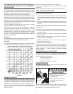
For appliance installation locations with elevations above 2000
feet, refer to HIGH ALTITUDE INSTALLATIONS section of this
manual for input reduction procedure.
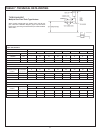
1. Attach a pressure gauge or a manometer to the manifold
pressure tap on the gas valve and refer to Table 3, page 8 for
correct manifold pressure.
2. Use this formula to “clock” the meter. Be sure that other gas
consuming appliances are not operating during this interval.
(3600/T) x H = Btuh
T = Time in seconds to burn one cubic foot of gas.
H = Btu’s per cubic foot of gas.
Btuh = Actual heater input.
Example: (Using SBD85500NE heater)
T = 7.56 seconds
H = 1050 Btu
Btuh = ?
(3600/7.56) X 1050 = 500,000 Btuh (Compare with the
SBD85500NE model and rating.)
Should it be necessary to adjust the gas pressure to the burners
to obtain the full input rate, the steps below should be followed:
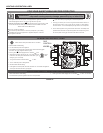
3. Remove the regulator adjustment sealing cap, g. 25, and adjust
the pressure by turning the adjusting screw with a screwdriver.
Clockwise to increase gas pressure and input rate.
Counterclockwise to decrease gas pressure and input rate.
4. “Clock” the meter as in step 2 above.
5. Repeat steps 3 and 4 until the specied input rate is achieved.
6. Turn the gas control knob to PILOT. Remove the pressure
gauge and replace the sealing cap and the threaded plug in
the pressure tap opening.
UNDER NO CIRCUMSTANCES SHOULD THE GAS INPUT
EXCEED THE INPUT SHOWN ON THE HEATER MODEL AND
RATING PLATE. OVERFIRING COULD RESULT IN DAMAGE
OR SOOTING OF THE HEATER.
VENTING SYSTEM
Examine the venting system every six months for obstructions
and/or deterioration of the vent piping.
Remove all soot or other obstructions from chimney which will
retard free draft.
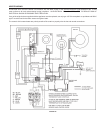
REMOTE STORAGE TANK TEMPERATURE CONTROL
The water temperature in the remote storage tank (if used) is
controlled by the storage tank temperature control. The sensing
element is mounted in the hot water storage tank, see Water
Piping Diagram section.
A change in water temperature in the storage tank lower than
the tank temperature control setting will cause the sensor to
activate the circulating pump. The pump then circulates the water
through the heater where the thermostat senses the drop in water
temperature and activates main burner operation of the appliance.
If the storage tank temperature control is out of calibration, replace
with new control.
SHOULD OVERHEATING OCCUR OR THE GAS SUPPLY FAIL
TO SHUT OFF, TURN OFF THE MANUAL GAS CONTROL VALVE
TO THE APPLIANCE.
TEMPERATURE-PRESSURE RELIEF VALVE TEST
It is recommended that the Temperature-Pressure Relief Valve
should be checked to ensure that it is in operating condition every
6 months.
MAINTENANCE