


23
Board waits 3 seconds and then shuts off power to the Silicon
Nitride Ignitor.
11. From the time the Silicon Nitride Ignitor’s power is shut off,
the Ignition Control Board waits 3 more seconds to monitor
the Flame Sensor.
12. If the Flame Sensor does not detect a strong enough ame,
the Ignition Control Board shuts off the Gas Valve and allows
the Exhaust Inducer to purge the unit for 20 seconds. At that
time, the Ignition Control Board restarts with step 7. It will try
and ignite the main burners 2 more times. If the unit does not
light, the Ignition Control Board will wait one hour and then
restart at step 3. This cycle will continue until the unit lights
or the power is shutoff to the unit.
13. If the Flame Sensor detects a strong ame, the Ignition Control
Board will allow the unit to operate until the thermostat is
satised.
14. Once the unit is satised, the Ignition Control Board will shut
off the Gas Valve and the unit will be in standby mode until
another call for heat is initiated by the thermostat.
See the ow chart on page 32 for more information.
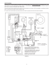
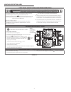
The following information will describe the Sequence of Operation
for this appliance.
1. Switch power on to unit.
2. Thermostat calls for heat.
3. Ignition Control Board performs diagnostic check on system
components.
4. On completion of diagnostics check, the Ignition Control Board
sends signal to Exhaust Inducer.
5. Exhaust Inducer begins drawing air through appliance closing
the Prover Switch.
6. On completion of Prover Switch engagement, the Ignition
Control Board begins the ignition cycle.
7. The Ignition Control Board provides power to the Silicon
Nitride Ignitor.
8. The Silicon Nitride Ignitor heats up for approximately 17 to
20 seconds.
9. At the end of Silicon Nitride Ignitor’s warm-up, the Ignition
Control Board opens the Gas Valve.
10. From the time the Gas Valve opens, the Ignition Control
IMPORTANT
A qualied person must perform the initial ring of the heater. At
this time the user should not hesitate to ask the individual any
questions which they may have in regard to the operation and
maintenance of the unit.
An Operational Checklist is included on page 33 of this manual.
By using this checklist the user may be able to make minor
operational adjustments and avoid unnecessary service calls.
However, the user should not attempt repairs which are not listed
under the USER column.
GENERAL
NEVER OPERATE THE HEATER WITHOUT FIRST BEING
CERTAIN IT IS FILLED WITH WATER AND A TEMPERATURE
AND PRESSURE RELIEF VALVE IS INSTALLED IN THE
RELIEF VALVE OPENING OF THE HEATER.
SHOULD OVERHEATING OCCUR OR THE GAS SUPPLY FAIL
TO SHUT OFF, TURN OFF THE MANUAL GAS CONTROL
VALVE TO THE APPLIANCE.
Before proceeding with the operation of the unit make sure
the water heater and system are lled with water and all air is
expelled.
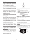
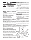
FILLING
1. Close the heater drain valve by turning handle clockwise.
2. Open a nearby hot water faucet to permit the air in the system
to escape.
3. Fully open the cold water inlet pipe valve allowing the heater
and piping to be lled.
4. Close the hot water faucet as water starts to ow.
5. The heater is ready to be operated.
OPERATION
THE GAS VALVE MUST HAVE BEEN IN THE OFF POSITION
FOR AT LEAST 5 MINUTES. This waiting period is an
important safety step. Its purpose is to permit gas that may
have accumulated in the combustion chamber to clear. IF YOU
DETECT GAS ODOR AT THE END OF THIS PERIOD DO NOT
PROCEED WITH LIGHTING. RECOGNIZE THAT GAS ODOR,
EVEN IF IT SEEMS WEAK, MAY INDICATE PRESENCE OF
ACCUMULATED GAS SOMEPLACE IN THE AREA WITH
RISK OF FIRE OR EXPLOSION. SEE THE FRONT PAGE FOR
STEPS TO BE TAKEN.
All gas and water lines must be leak tested and open.
Read SEQUENCE OF OPERATION section of this manual prior
to lighting and operating this appliance.
With above conditions satised, start the unit in accordance with
the instructions on the operating label attached to the heater. For
your convenience a copy of the instructions are shown on page
24. Each heater is equipped with an ignition control board. The
controller will try three times to light the main burner before going
into lockout. After the controller tries three times, it will wait one
hour before trying to light the unit again. This cycle will continue
until the main burners are ignited or the unit is shut down.
ADJUSTMENTS
ON INITIAL STARTUP SOME ADJUSTMENTS ARE NECESSARY.
1. CHECK MANIFOLD AND INLET GAS PRESSURES.
2. CYCLE CHECK - CHECK AT LEAST ONE BURNER
OPERATION - WHEN THERMOSTAT IS SATISFIED,
BURNER WILL SHUT OFF AND INDUCER WILL STOP
RUNNING. ON CALL FOR HEAT - THE INDUCER WILL
COME ON AND CLOSE THE PRESSURE SWITCH AND THE
IGNITION SEQUENCE DESCRIBED ABOVE WILL BEGIN,
SEE “SEQUENCE OF OPERATION”.
SEQUENCE OF OPERATION