


25
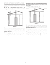
CHECK VENTING
The following steps shall be followed with each appliance
connected to the venting system placed in operation, while any
other appliances connected to the venting system are not in
operation.
1. Seal any unused openings in the venting system.
2. Inspect the venting system for proper size and horizontal pitch,
as required in the National Fuel Gas Code, ANSI Z223.1or the
CAN/CGA B149 Installation Codes and these instructions.
Determine that there is no blockage or restriction, leakage,
corrosion and other deciencies which could cause an unsafe
condition.
3. So far as is practical, close all building doors and windows
and all doors between the space in which the water heater(s)
connected to the venting system are located and other spaces
of the building. Turn on all appliances not connected to the
venting system. Turn on all exhaust fans, such as range hoods
and bathroom exhausts, so they shall operate at maximum
speed. Close replace dampers.
4. Follow the lighting instruction. Place the water heater being
inspected in operation. Adjust thermostat so appliance shall
operate continuously.
5. Test for spillage at the burner level after 5 minutes of main
burner operation.
6. After it has been determined that each water heater connected
to the venting system properly vents when tested as outlined
above, return doors, windows, exhaust fans, replace dampers
and any other gas burning appliance to their previous conditions
of use.
7. If improper venting is observed during any of the above tests,
the venting system must be corrected.
FAILURE TO CORRECT BACK DRAFTS MAY CAUSE AIR
CONTAMINATION AND UNSAFE CONDITIONS.
• If the back draft cannot be corrected by the normal method or
if a suitable draft cannot be obtained, a blower type ue gas
exhauster must be employed to assure proper venting and
correct combustion.
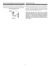
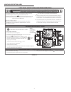
CHECK THE IGNITER ASSEMBLY
At least once a year, check the igniter assembly, Figure 23, and
the main burner, Figure 24, for proper operation. Refer to the
following igniter assembly and main burner sections.
IGNITER ASSEMBLY
For access to igniter assembly, unfasten two screws to burner
cover and remove. Locate the burner with the igniter assembly
and remove screw holding burner to manifold. Slide burner out
to access igniter assembly.
Servicing of the igniter assembly includes keeping the igniter free
of lint, scale or any other foreign debris.
FIGURE 23
MAIN BURNER
The main burner, figure 24, should display the following
characteristics:
• Cause rapid ignition and carry across entire burner.
• Give reasonably quiet operation during ignition, burning, and
extinction.
• Cause no excessive lifting of ame from burner ports.
FIGURE 24
If the preceding burner characteristics are not evident, check for
accumulation of lint, scale or other foreign debris that restricts or
blocks the air openings to the burner or heater.
NOTE:
1. Remove main burners from unit.
2. Check that burner venturi and ports are free of foreign debris.
3. Clean burners with bristle brush and/or vacuum cleaner - DO
NOT distort burner ports or pilot location.
4. Reinstall burners in unit. Make sure front and rear of burners
are installed correctly in burner support brackets.
Also check for good ow of combustion and ventilating air to the
unit. Maintain a clear area around the heater at all times.
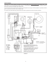
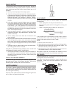
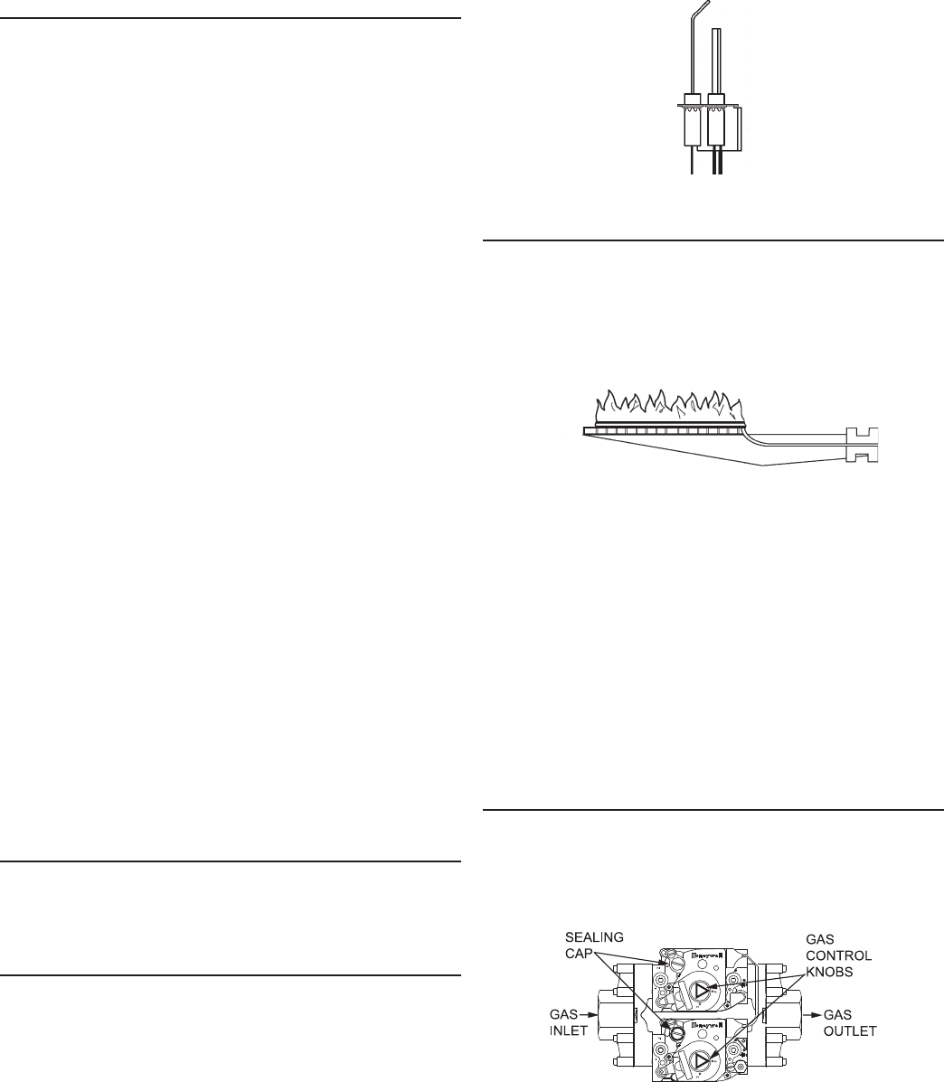
GAS VALVES
Figure 25 shows the type of combination manual gas control valve
and regulator used on these heaters.
If the gas valve becomes defective, repairs should not be
attempted. A new valve should be installed in place of the
defective one.
FIGURE 25