


16
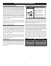
vent with an oil burning furnace, the vent pipe should enter
the smaller common vent or chimney at a point above the
large vent pipe.
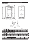
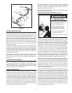
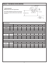
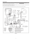
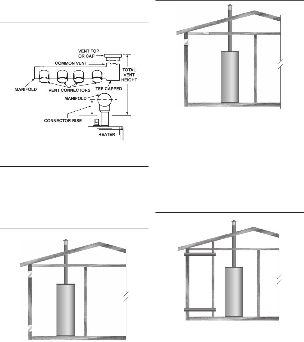
MULTIPLE HEATER MANIFOLD
Figure 13 and Table 7 should be used for horizontally manifolding
two or more heaters.
FIGURE 13
FRESH AIR OPENINGS FOR CONFINED SPACES
The following instructions shall be used to calculate the size,
number and placement of openings providing fresh air for
combustion, ventilation and dilution in conned spaces. The
illustrations shown in this section of the manual are a reference
for the openings that provide fresh air into conned spaces
only. DO NOT refer to these illustrations for the purpose of vent
installation. See Venting Installation on page 15 for complete
venting installation instructions.
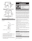
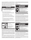
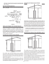
OUTDOOR AIR THROUGH TWO OPENINGS
FIGURE 14
The conned space shall be provided with two permanent
openings, one commencing within 12 inches (300 mm) of the top
and one commencing within 12 inches (300 mm) of the bottom of
the enclosure. The openings shall communicate directly with the
outdoors. See Figure 14.
Each opening shall have a minimum free area of 1 square inch
per 4,000 Btu/hr (550 mm2 per kW) of the aggregate input rating
of all appliances installed in the enclosure. Each opening shall
not be less than 100 square inches (645 cm2).
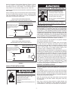
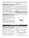
OUTDOOR AIR THROUGH ONE OPENING
FIGURE 15
Alternatively a single permanent opening, commencing within 12
inches (300 mm) of the top of the enclosure, shall be provided. See
Figure 15. The water heater shall have clearances of at least 1 inch
(25 mm) from the sides and back and 6 inches (l50 mm) from the
front of the appliance. The opening shall directly communicate with
the outdoors or shall communicate through a vertical or horizontal
duct to the outdoors or spaces that freely communicate with the
outdoors and shall have a minimum free area of the following:
1. 1 square inch per 3000 Btu/hr (733 mm
2
per kW) of the total
input rating of all appliances located in the enclosure, and
2. Not less than the sum of the areas of all vent connectors in
the space.
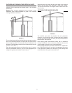
OUTDOOR AIR THROUGH TWO HORIZONTAL DUCTS
FIGURE 16
The conned space shall be provided with two permanent
horizontal ducts, one commencing within 12 inches (300 mm) of
the top and one commencing within 12 inches (300 mm) of the
bottom of the enclosure. The horizontal ducts shall communicate
directly with the outdoors. See Figure 16.
Each duct opening shall have a minimum free area of 1 square
inch per 2,000 Btu/hr (1100 mm
2
per kW) of the aggregate input
rating of all appliances installed in the enclosure.
When ducts are used, they shall be of the same cross sectional
area as the free area of the openings to which they connect.
The minimum dimension of rectangular air ducts shall be not less
than 3 inches.