


19
WATER HEATER INSTALLATION
This water heater is provided with a properly rated/sized and
certied combination temperature - pressure (T&P) relief valve
by the manufacturer. See Temperature-Pressure Relief Valve
on pages 13-14 for information on replacement and other
requirements.
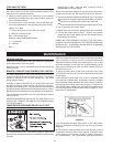
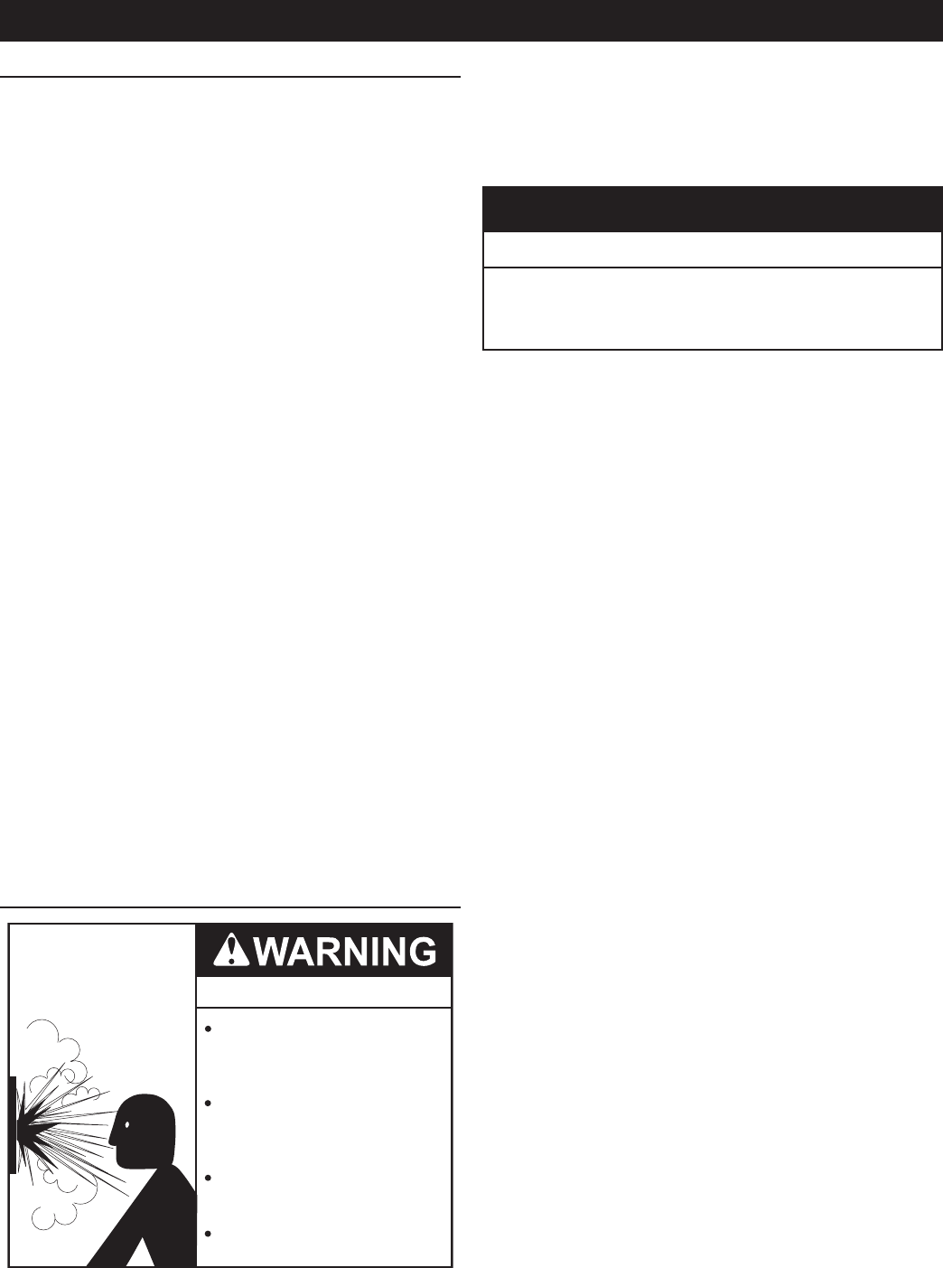
Water Damage Hazard
Temperature-Pressure Relief Valve discharge
pipe must terminate at adequate drain.
•
CAUTION
Install a discharge pipe between the T&P valve discharge opening
and a suitable oor drain. Do not connect discharge piping
directly to the drain unless a 6” (15.2 cm) air gap is provided.
To prevent bodily injury, hazard to life, or property damage, the
relief valve must be allowed to discharge water in adequate
quantities should circumstances demand. If the discharge pipe is
not connected to a drain or other suitable means, the water ow
may cause property damage.
T&P Valve Discharge Pipe Requirements:
• Shall not be smaller in size than the outlet pipe size
of the valve, or have any reducing couplings or other
restrictions.
• Shall not be plugged or blocked.
• Shall not be exposed to freezing temperatures.
• Shall be of material listed for hot water distribution.
• Shall be installed so as to allow complete drainage of both
the Temperature-Pressure Relief Valve and the discharge
pipe.
• Must terminate a maximum of six inches above a oor
drain or external to the building. In cold climates, it is
recommended that the discharge pipe be terminated at an
adequate drain inside the building.
• Shall not have any valve or other obstruction between the
relief valve and the drain.
The type, size and location of the relief valves must be in
accordance with local codes. The locations of the relief valves
shown in the installation diagrams are typical. See pages 34-48.
The heater has a factory installed high temperature limit switch
and temperature and pressure relief valve.
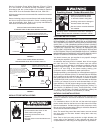
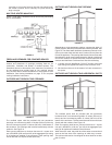
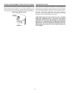
Cold water lines to heater should be installed as shown in
order to minimize gravity circulation of hot water to building
cold water lines.
A listed temperature and pressure relief valve of adequate capacity
is installed on the heater. The locations shown in the installation
diagrams on pages 34-48 are typical.
The discharge opening of the temperature and pressure relief
valve must be piped to an open drain and should not be subject
to freezing temperatures.
Install in accordance with all local codes.
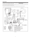
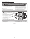
WATER LINE CONNECTIONS
This manual provides detailed installation diagrams (see pages
34-48 of this manual) for typical methods of application for the
water heater(s).
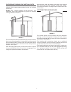
WATER (POTABLE) HEATING AND SPACE HEATING
1. All piping components connected to this unit for space
heating applications shall be suitable for use with potable
water.
2. Toxic chemicals, such as those used for boiler treatment,
shall NEVER be introduced into this system.
3. This unit may NEVER be connected to any existing
heating system or component(s) previously used with a
non-potable water heating appliance.
4. When the system requires water for space heating at
temperatures higher than required for domestic water
purposes, a tempering valve must be installed. Please
refer to installation diagrams on pages 34-48 of this manual
for suggested piping arrangements.
THERMOMETERS (NOT SUPPLIED)
Thermometers should be obtained and eld installed as shown in
the installation diagrams.
Thermometers are installed in the system as a means of detecting
the temperature of the outlet water supply.
WATER PIPING DIAGRAMS
This manual provides detailed water piping diagrams for typical
methods of application for the water heaters, see Water Piping
Diagrams beginning on page 34.
The water heater may be installed by itself, or with a separate
storage tank, on both single and two-temperature systems. When
used with a separate storage tank, the circulation may be either
by gravity or by means of a circulating pump. When a circulating
pump is used it is important to note that the ow rate should be
slow so that there will be a minimum of turbulence inside the heater.
Adjust ow by throttling a full port ball valve installed in the
circulating line on the outlet side of the pump. Never throttle ow
on the suction side of a pump.
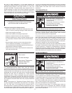
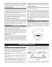
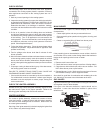
T&P VALVE DISCHARGE PIPE
Explosion Hazard
Temperature-Pressure Relief Valve
must comply with ANSI Z21.22-
CSA 4.4 and ASME code.
Properly sized temperature-
pressure relief valve must be
installed in opening provided.
Can result in overheating and
excessive tank pressure.
Can cause serious injury or death.