


22
GAS PIPING
Contact your local gas service company to ensure that adequate
gas service is available and to review applicable installation
codes for your area.
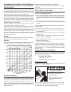
Size the main gas line in accordance with Table 9. The gures shown
are for straight lengths of pipe at 0.5 in. W.C. pressure drop, which is
considered normal for low pressure systems. Note: Fittings such as
elbows, tees and line regulators will add to the pipe pressure drop.
Also refer to the latest version of the National Fuel Gas Code.
Schedule 40 Metallic Pipe is the preferred material for the gas
line of this water heater. It is imperative to follow the sizing
recommendations in the latest version of the National Fuel Gas
Code if Corrugated Stainless Steel Tubing (CSST) is used as the
gas line for this water heater.
THE HEATER IS NOT INTENDED FOR OPERATION AT HIGHER
THAN 14.0” W.C.- NATURAL GAS, (1/2 POUND PER SQUARE
INCH GAGE) SUPPLY GAS PRESSURE. EXPOSURE TO
HIGHER SUPPLY PRESSURE MAY CAUSE DAMAGE TO THE
GAS VALVE WHICH COULD RESULT IN FIRE OR EXPLOSION.
IF OVERPRESSURE HAS OCCURRED SUCH AS THROUGH
IMPROPER TESTING OF GAS LINES OR EMERGENCY
MALFUNCTION OF THE SUPPLY SYSTEM, THE GAS VALVE
MUST BE CHECKED FOR SAFE OPERATION. MAKE SURE THAT
THE OUTSIDE VENTS ON THE SUPPLY REGULATORS AND THE
SAFETY VENT VALVES ARE PROTECTED AGAINST BLOCKAGE.
THESE ARE PARTS OF THE GAS SUPPLY SYSTEM, NOT THE
HEATER. VENT BLOCKAGE MAY OCCUR DURING ICE STORMS.
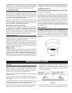
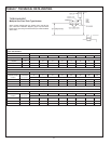
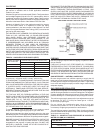
TABLE 9 - GAS SUPPLY PIPE LENGTH (FEET)
Schedule 40 metallic
pipe nominal dia.
500,000 btu/hr input rate
MAXIMUM EQUIVALENT PIPE LENGTH (FEET)
Natural Gas Propane
3/4" - 10
1" 10 40
1 1/4" 60 150
1 1/2" 150 350
2" 200 400
2 1/2" 200 400
Natural Gas: 0.60 Specic Gravity, 0.50"W.C. pressure drop
Propane Gas: 1.50 Specic Gravity, 0.50"W.C. pressure drop
IT IS IMPORTANT TO GUARD AGAINST GAS VALVE FOULING
FROM CONTAMINANTS IN THE GAS WAYS. SUCH FOULING
MAY CAUSE IMPROPER OPERATION, FIRE OR EXPLOSION.
IF COPPER SUPPLY LINES ARE USED THEY MUST BE
INTERNALLY TINNED AND CERTIFIED FOR GAS SERVICE.
BEFORE ATTACHING THE GAS LINE, BE SURE THAT ALL GAS
PIPE IS CLEAN ON THE INSIDE.
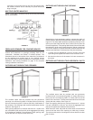
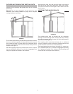
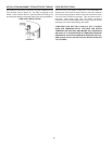
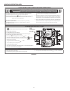
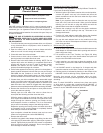
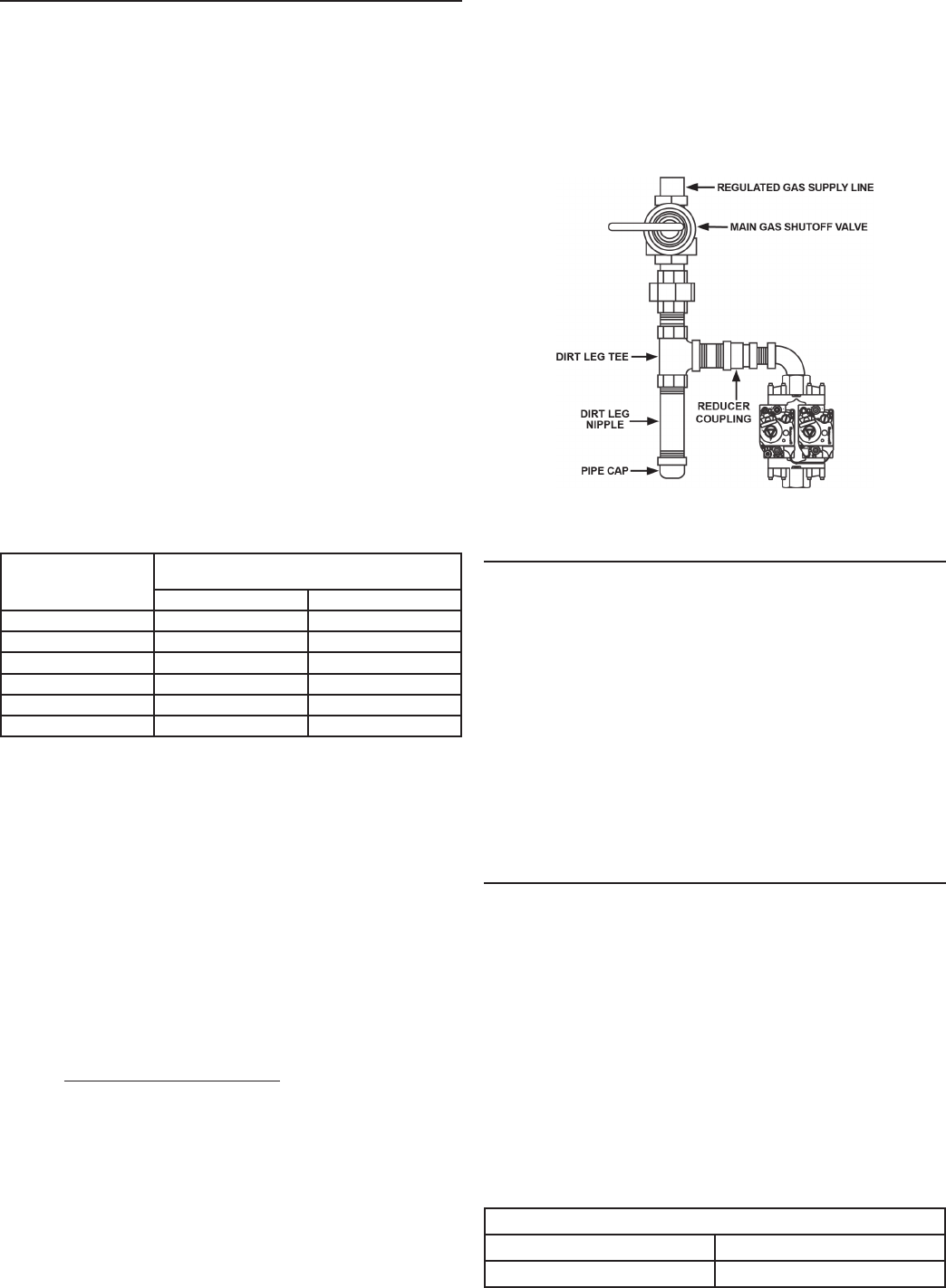
TO TRAP ANY DIRT OR FOREIGN MATERIAL IN THE GAS
SUPPLY LINE, A DIRT LEG (SOMETIMES CALLED SEDIMENT
TRAP OR DRIP LEG) MUST BE INCORPORATED IN THE
PIPING (SEE FIG. 21). THE DIRT LEG MUST BE READILY
ACCESSIBLE AND NOT SUBJECT TO FREEZING CONDITIONS.
INSTALL IN ACCORDANCE WITH RECOMMENDATIONS OF
SERVING GAS SUPPLIERS. REFER TO THE LATEST VERSION
OF THE NATIONAL FUEL GAS CODE.
To prevent damage, care must be taken not to apply too much
torque when attaching gas supply pipe to gas valve inlet.
Apply joint compounds (pipe dope) sparingly and only to the male
threads of pipe joints. Do not apply compounds to the rst two threads.
Use compounds resistant to the action of liqueed petroleum gases.
BEFORE PLACING THE HEATER IN OPERATION, CHECK FOR
GAS LEAKAGE. Use soap and water solution or other material
acceptable for the purpose in locating the leaks. DO NOT USE
MATCHES, CANDLES, FLAME OR OTHER SOURCES OF
IGNITION FOR THIS PURPOSE.
DISCONNECT THE HEATER AND ITS MANUAL GAS SHUTOFF
VALVE FROM THE GAS SUPPLY PIPING SYSTEM DURING ANY
SUPPLY PRESSURE TESTING EXCEEDING 1/2 PSIG. GAS
SUPPLY LINE MUST BE CAPPED WHEN DISCONNECTED
FROM THE HEATER. FOR TEST PRESSURES OF 1/2 PSIG OR
LESS THE APPLIANCE NEED NOT BE DISCONNECTED, BUT
MUST BE ISOLATED FROM THE SUPPLY PRESSURE TEST
BY CLOSING THE MANUAL GAS SHUTOFF VALVE.
GAS PIPING AND DIRT LEG INSTALLATION
FIGURE 21
PURGING
Gas line purging is required with new piping or systems in which
air has entered.
PURGING SHOULD BE PERFORMED BY PERSONS
EXPERIENCED IN THIS TYPE GAS SERVICE. TO AVOID RISK
OF FIRE OR EXPLOSION, PURGE DISCHARGE MUST NOT
ENTER CONFINED AREAS OR SPACES WHERE IGNITION CAN
OCCUR. THE AREA MUST BE WELL VENTILATED AND ALL
SOURCES OF IGNITION MUST BE INACTIVATED OR REMOVED.
GAS METER SIZE — NATURAL GASES ONLY
Be sure the gas meter has sufcient capacity to supply the full
rated gas input of the water heater as well as the requirements of
all other gas red equipment supplied by the meter. If gas meter
is too small, ask the gas company to install a larger meter having
adequate capacity.
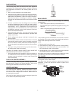
GAS PRESSURE REGULATOR
The gas pressure regulator is built into the gas valve and is equipped to
operate on the gas specied on model and rating plate. The regulator
is factory adjusted to deliver gas to burner at correct water column
pressure allowing for a nominal pressure drop through the controls.
The minimum gas supply pressure for input adjustment must not
be less than 4.5” W.C. (1.12 kPa) for natural gas or 11.0"W.C.
(2.74 kPa) for propane gas.
Do not subject the combination gas valve to inlet gas
pressures of more than 14.0” W.C. (3.48 kPa). A service regulator
is necessary if higher gas pressures are encountered.
The manifold gas pressure specied in Table 10 refers to the gas
pressure measured at the pressure tap of the automatic gas valve
when the burners are ring.
TABLE 10 - MANIFOLD GAS PRESSURE IN INCHES OF
WATER COLUMN (ALL MODELS*)
TYPE OF GAS
NATURAL PROPANE
3.5 (0.87 kPa) 10.0 (2.49 kPa)