


GB300 BOILER INSTALLATION AND OPERATION INSTRUCTIONS
Page 45
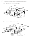
Burner Installation
1. DO NOT install damaged or badly corroded burners,
replace them.
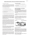
2. Install the burners by sliding the rear of the burner
tube into the slot located in the base rear panel. Slide
the burner into the slot far enough so that the burner
bracket clears the orifice on the manifold. Pull the burner
back onto the orifice making sure that the notch in the
crimped portion of the burners engages the rear burner
base panel locking it into place.
3. Replace the front grill(s).
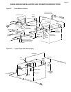
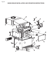
Heat Exchanger Cleaning
The burners should be removed to protect them from
falling rust and scale. Follow the BURNER REMOVAL
instructions in this manual.
1. Remove the front grill(s) and front access panel(s).
2. Remove the clean out covers and insulation, Figure
55 & 56.
3. Clean each flue passage with a wire brush.
4. Vacuum out the burner base and clean and inspect
all of the components. Replace any damaged or badly
corroded parts.
5. Replace the insulation and clean out covers,
6. Replace the front access panel.
7. Install the burners following the BURNER
INSTALLATION procedure outlined in this section.
8. Replace the front grill(s).
Vent System
Thoroughly inspect the vent system for any signs of
blockage, corrosion or leakage. Immediately replace any
unsound vent system piping.
Controls
Use the BOILER OPERATION and BOILER CHECKING
AND ADJUSTMENT sections of this manual for
reference.
1. Check the thermostat or operating controls for
proper operation.
2. A float type low water cutoff device must be flushed
out.
3. The relief valve should vent water when the test lever
is lifted. It should not weep or discharge water at normal
system pressure. NEVER try to clean or repair the relief
valve! If the valve fails to operate properly, replace it!
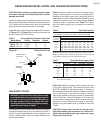
4. The aquastat high limit controls the maximum water
temperature in the boiler. It is adjustable from 140°F
(60°C) to 240°F (116°C). If the water temperature
reaches the set temperature before the demand for heat
has been met, the aquastat high limit should shut the
boiler off. The water temperature should never exceed
the maximum set point of 240°F (60°C). The aquastat
high limit cannot be repaired. If it fails to function
properly replace it.
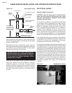
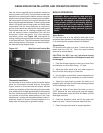
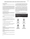
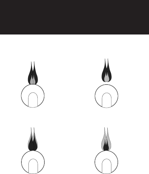
5. Visually check the pilot and main burner flames to
ensure proper operation, see Figure 103 & 104.
WARNING: Yellow, floating flames indicate a lack
of combustion air. Do not operate the boiler until
the problem is solved or severe personal injury
or death may occur!
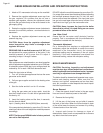
Figure 104 Main Burner Flames
NORMAL
(HARD FLAME)
LIFTING
(TOO MUCH AIR)
YELLOW TIPPING
(MARGINAL)
YELLOW FLAME
(TOO LITTLE AIR)