


GB300 BOILER INSTALLATION AND OPERATION INSTRUCTIONS
Page 19
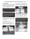
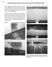
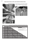
To ensure that the assembled sections will be centered
on the burner base the cast iron sections should be
assembled from the midpoint of the burner base outward.
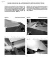
On boilers having an even number of sections the first
intermediate section should be placed so it’s side surface
lines up with the midpoint marked on the burner base
front and rear panels, Figures 31 and 32.
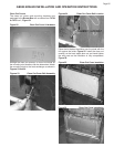
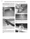
For boilers having an odd number of sections, the
centerline of the first intermediate section should line up
directly with the midpoint marks on the burner base front
and rear panels, Figures 33 and 34.
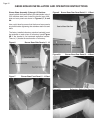
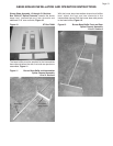
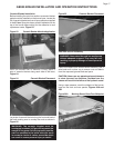
Refer to Table 3 for the location of the intermediate
sections with steam riser tappings, the flue collector
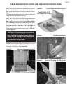
brackets and the front jacket channel bracket. With the
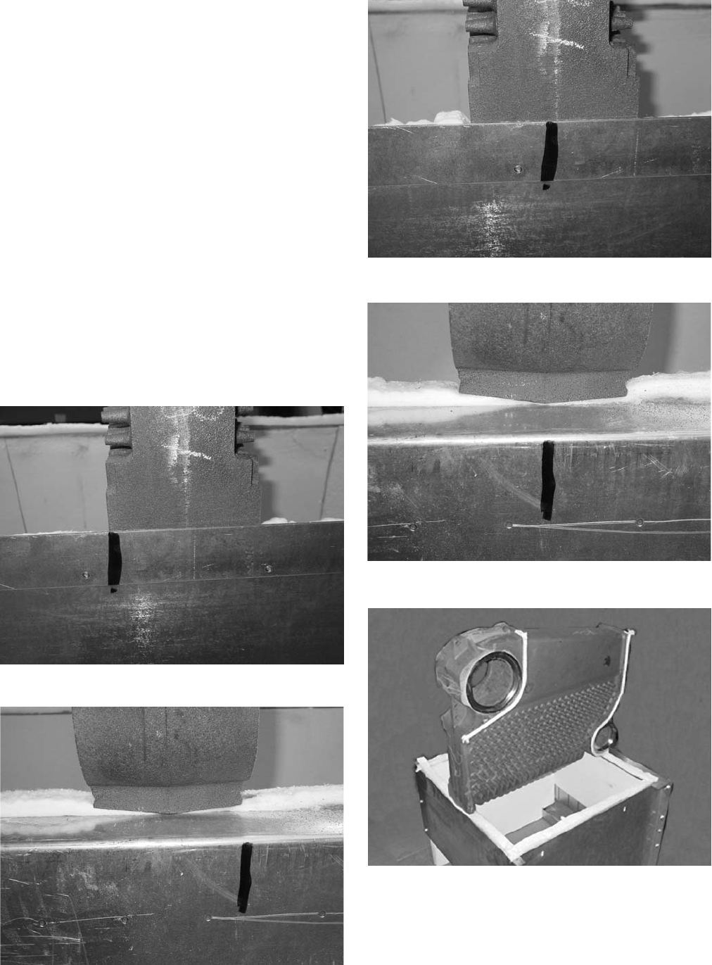
rope seal in place set the first section on the base making
sure that the section is supported and will not fall over.
The large top port should be above the front of the burner
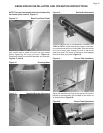
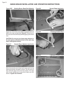
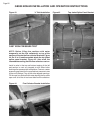
base, Figure 35. Set the hydronic seals from the X1 Box
in the port openings before carefully bringing the next
section along side of it, Figures 36 and 37.
Figure 31 Front View - Even Numbered Models
Figure 32 Rear View - Even Numbered Models
Figure 33 Front View - Odd Numbered Models
Figure 34 Rear View - Odd Numbered Models
Figure 35 Section Placement on Burner Base
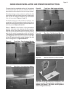
CAUTION: Do not use adhesives or sealants on the
hydronic gaskets. The application of adhesives or
sealants may result in the failure of the hydronic
seals voiding the warranty!