


GB300 BOILER INSTALLATION AND OPERATION INSTRUCTIONS
Page 26
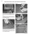
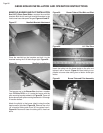
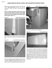
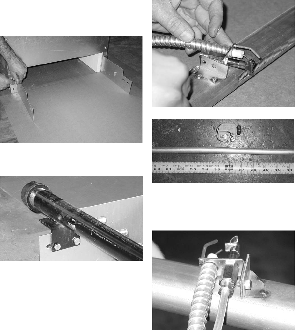
MANIFOLD, BURNER AND PILOT INSTALLATION
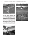
Box 63273, Base Panel Sides, contains the manifold
brackets. Bolt the left and right manifold brackets to the
front burner base side panel flanges, Figures 16 and 57.
Figure 57 Manifold Bracket Attachment
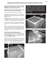
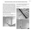
Place the manifold on the brackets and bolt it to the
brackets leaving the 5/16 bolts finger tight, Figure 58.
Figure 58 Manifold Installations
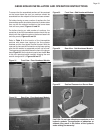
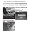
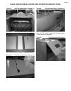
The burners are in the Burner Box that has a number
from 72724 to 72731 on it. Locate the burner with the
pilot mounting bracket welded to it, Figure 59. There will
be two burners with pilot mounting brackets for 13 through
21 section boilers.
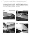
Attach the pilot(s) to the burner tube(s) using the allen
head screw(s) provided, Figure 59. Remove the roll of
1/4" aluminum tubing and cut an 36" long piece from it,
Figure 60. Ream and clean the tubing so it’s free from
burrs.
Figure 59 Burner Tube w/ Pilot Bkt. and Pilot
Figure 60 1/4" Pilot Tube
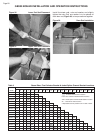
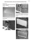
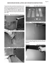
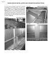
Insert the tubing into the brass ferule on the pilot and
tighten it with a wrench, Figure 61. Bend tubing to run
parallel to burner tube exiting front of boiler. Avoid tight
radius.
Figure 61 Burner Tube and Pilot Assembly