


GB300 BOILER INSTALLATION AND OPERATION INSTRUCTIONS
Page 36
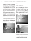
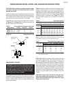
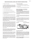
Piping For Use With Cooling Units
The boiler, when used in connection with a refrigeration
system, must be installed so the chilled medium is piped
in parallel with the boiler. Appropriate valves must be
used to prevent the chilled water from entering the boiler.
When a boiler is connected to a heating coil that may
be exposed to refrigerated air from an air handling
device, the piping system must be equipped with flow-
control valves or some other automatic means of
preventing gravity circulation of the boiler water during
the cooling cycle.
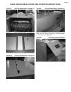
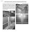
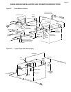
Steam Boiler Piping Connections
Table 3, contains the steam riser location schedule. Riser,
equalizer and header pipe sizes are located in Table 5.
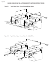
A typical single boiler piping arrangement is shown in
Figure 95. Figures 97 & 97A contain typical piping
diagrams for steam boilers in battery. The steam piping
should be pitched so the condensate flows in the direction
of steam travel.
Table 4 Supply & Return Pipe Sizing
Boiler Model Supply Size (in) Return Size (in)
5 - 10 section 3" 3"
11 - 21 section 4" 3"
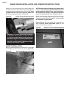
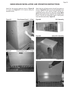
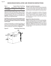
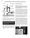
Install the Pressure Relief Valve in the 1 1/2 NPT
opening in the top of the end section opposite the gas
controls. Pipe the discharge of the Pressure Relief Valve
to prevent scalding in the event of a discharge, see
Figure 93. The discharge piping must be sized the same
as the Pressure Relief Valve outlet.
CAUTION: If the relief valve must be installed on the
same end as the gas controls, provisions to protect
the controls from water in the event of a discharge
must be made.
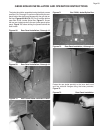
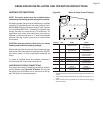
Locate the Theraltemeter, Low Water Cutoff Device, Hi
Limit Control and Operating Control per Figures 94 & 95.
Optional controls must be installed in accordance with the
control manufacturers instructions and Figure 94.
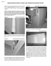
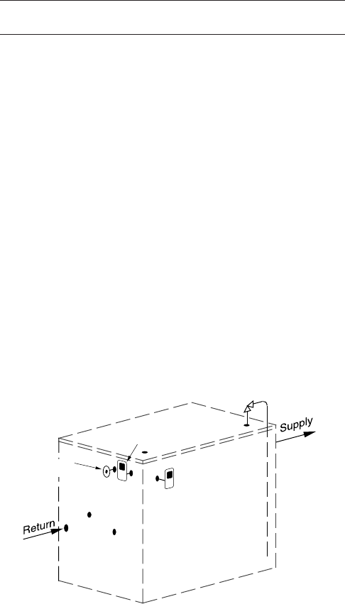
Figure 95 Single Water Boiler Piping
Hi Limit
Control
ASME
Safety
Valve
Operating
Control
Temperature
Pressure Gage