


GB300 BOILER INSTALLATION AND OPERATION INSTRUCTIONS
Page 20
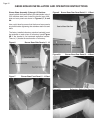
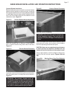
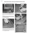
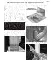
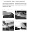
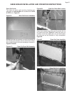
Figure 36 Lower Port Seal Placement
Figure 37 Upper Port Seal Placement
FCB &
JSB
FCB &
JSB
FCB &
JSB
FCB &
JSB
FCB &
JSB
FCB &
JSB
FCB &
JSB
FCB &
JSB
FCB &
JSB
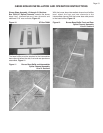
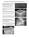
Boiler
Section Numbered from Left to Right
Model 123456789101112131415161718192021
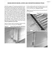
GB300-5 FCB 4P FCB LOCATION OF ITEM
GB300-6 FCB 5P FCB - 3" Steam Riser Section Location
GB300-7 FCB 6P FCB FCB - Flue Collector Bracket Section Location
GB300-8 FCB 7P FCB JSB -
Jacket Splice Channel Bracket Section Location
GB300-9 FCB 8P FCB #P - Pilot Burner Tube Location
GB300-10 FCB 9P FCB # Represents burner position from LH side of boiler
GB300-11 FCB 10P FCB
GB300-12 FCB 11P FCB
GB300-13 FCB 6P 19P FCB
GB300-14 FCB 7P 20P FCB
GB300-15 FCB 7P 22P FCB
GB300-16 FCB 8P 23P FCB
GB300-17 FCB 8P 25P FCB
GB300-18 FCB 9P 26P FCB
GB300-19 FCB 9P 28P FCB
GB300-20 FCB 10P 29P FCB
GB300-21 FCB 10P 31P FCB
Table 3 Steam Riser, Flue Collector Bracket & Jacket Splice Channel Bracket Locations
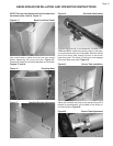
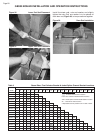
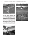
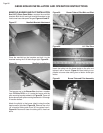
Install the draw rods, nuts and washer and slightly
tighten the nuts. Only one washer is to be placed on
each draw rod, Figure 38, to torque sections together.
Figure 38 Draw Rod Installation