


GB300 BOILER INSTALLATION AND OPERATION INSTRUCTIONS
Page 15
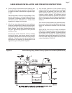
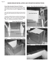
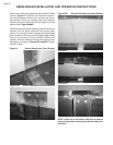
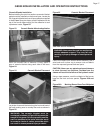
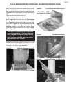
Figure 18 Manifold Attachments
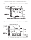
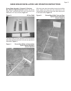
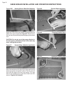
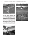
Locate the Burner Box. It is marked with a number from
72724 to 72731. Install three burner tubes in the base,
one on each end and one in the middle. Slide the closed
end of the burner tube through the slot in the burner
base rear panel. The notch in the burner must engage
the burner base rear panel, Figure 19.
Figure 19 Burner Tube Installation
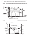
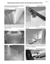
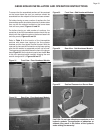
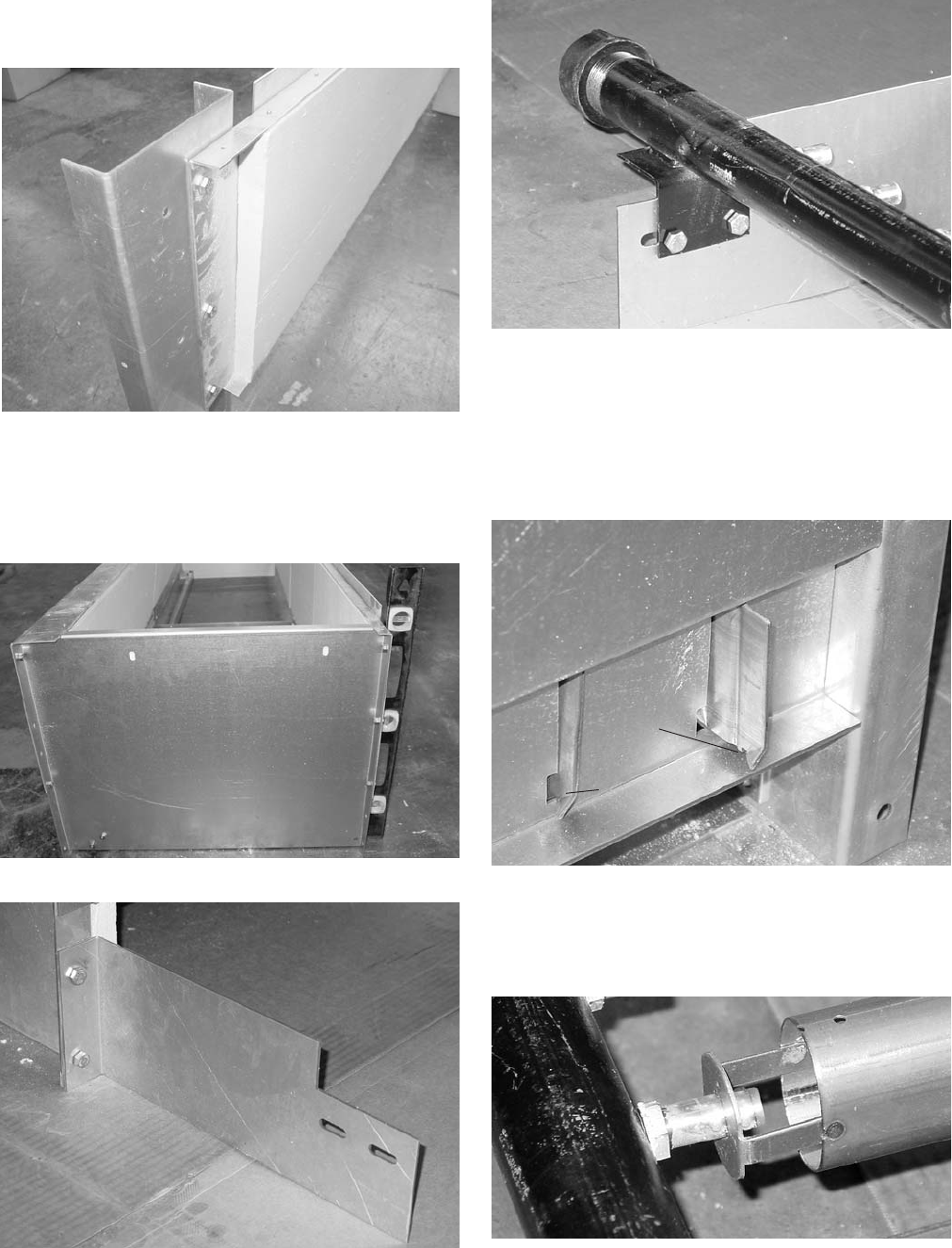
Adjust the manifold and base so the burner tube orifice
bracket is approximately in the middle of the orifice on
all three burners, Figure 20.
Figure 20 Burner Tube Adjustment
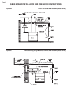
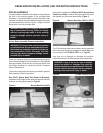
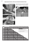
NOTE: The base front panels bolt to the inside of the
front base splice channel, Figure 15.
Figures 15 Base Front Panel Detail
Use a spirit level to plumb the front and rear panels
before tightening the nuts and bolts, Figure 16.
Temporarily attach the manifold brackets and manifold,
Figures 17 and 18.
Figure 16 Plumbing Base
Figure 17 Manifold Bracket Attachment
Notch
Notch
Engaged
•
•