


GB300 BOILER INSTALLATION AND OPERATION INSTRUCTIONS
Page 23
NOTE: All assembled boiler sections shall pass the
hydrostatic tests prescribed in Section IV of the
ASME Boiler and Pressure Vessel Code.
CAUTION: Do not connect any boiler controls during
the pressure test or they will be damaged!
Completed boiler blocks must be tested as follows:
Steam Boilers -
the assembled boiler sections shall be
subjected to a hydrostatic test pressure of not less than
45 psig,
315 kPa
.
Water Boilers -
the assembled boiler sections shall be
subjected to a hydrostatic test pressure of not less than
1 1/2 times the maximum allowable working pressure.
The hydrostatic pressure shall not exceed the required
test pressure by more than 10 psig,
70 kPa
during the
test.
Maintain the test pressure while carefully checking for
leaks. If a leak is found it must be eliminated. Once the
cast iron sections have proven to be watertight drain them
and remove the plugs from any tappings that will be used
in service.
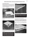
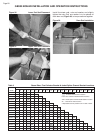
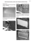
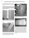
FLUE COLLECTOR INSTALLATION
A single draft hood is used on the 5 through 12 section
boilers, two are used on the 13 to 21 section boilers.
The Draft Hood(s) are packed in a box marked with a
number from 63187 to 63194.
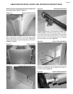
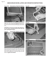
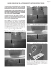
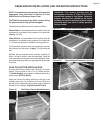
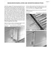
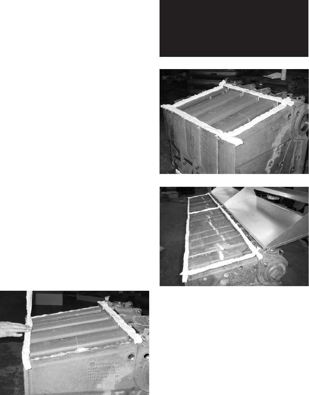
Apply two coats of the spray adhesive to the top of the
casings where the flue collectors will rest. When the
second coat of adhesive is tacky place strips of ceramic
blanket on the castings, Figures 46 and 47A & B.
Figure 46
Flue Collector Ceramic Blanket Placement
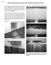
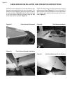
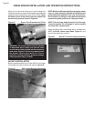
WARNING: The ceramic blanket must be
overlapped as shown in Figure 47A & B to
prevent the escape of flue gases. Failure to
properly seal the flue collector to the boiler
sections can result in excessive levels of carbon
monoxide which can result in severe personal
injury or death!
Figure 47A
Ceramic Blanket Placement 5-12 Sect.
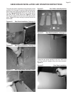
Figure 47B
Ceramic Blanket Placement 13-21 Sect.