


smoke and dry soot formation in the fire box.
F. If smoke reading is satisfactory, but CO
2
can not be
increased to a satisfactory level (12%) or overfire draft of
0
.02" W.C. can not be obtained, check for proper sealing
between sections, between the hinged burner mounting
door and front section, around burner blast tube and
a
round flue collector and collar. If seal is not satisfactory,
reseal with furnace putty or silicone with a temperature rat-
ing of at least 400° F. (All safety precautions indicated on
material package must be followed.)
G. Once burner and draft have been set up, then smoke, CO
2
and stack temperature should be checked and recorded. If
s
moke is greater than trace, review the burner instructions
and replace the nozzle if necessary. Normal smoke to be
expected is zero to a trace.
H. Make sure that the observation port cover is closed and
the screw is tightened.
CLEANING AND FILLING A NEW WATER BOILER
I. There are a number of commercial preparations available
from your distributor for cleaning and for corrosion protection
conditioning the internal (waterside) surfaces of boilers.
Follow the preparation manufacturer’s instructions.
DANGER: Use CAUTION when handling chemicals and
draining hot water from a boiler. Scalding water and/or
chemicals can cause permanent injury to the skin, eyes
and respiratory system.
II. Filling and venting the water boiler after cleaning
A. Refill the system with fresh water.
B. Bring water temperature to at least 180° F promptly.
C. Circulate water through entire system.
D. Vent the system, including the radiation.
E. The boiler is now ready to be put into service or on
standby.
F. If brand name air-control devices are used, venting
instructions furnished with the devices should
be followed.
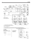
XL-2000
8
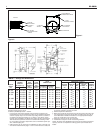
XL-20 XL-30
XL-40
XL-50
5.5 7.0
8.5 10.0
W
ATER CONTENT OF BOILER (GALLONS)
3/8 — — — 0.430 0.0075
1/2 40 0.622 0.0157 0.545 0.0121
5/8 — — — 0.666 0.0181
3/4 40 0.824 0.0277 0.785 0.0251
1 40 1.049 0.0449 1.025 0.0429
1 1/4 40 1.380 0.0779 1.265 0.0653
1 1/2 40 1.610 0.106 1.505 0.0924
2 40 2.067 0.174 1.985 0.161
2 1/2 40 2.469 0.249 2.465 0.248
3 40 3.068 0.384 2.945 0.354
Nominal
Pipe
Siz
e
Inches
Schedule
No
.
Inside
Diameter
Inches
Gallons
per
Lin. Ft.
Inside
Dia.
Inches
Gallons
per
Lin.
ft..
Standard Steel Pipe Type L Copper Tube
VOLUME OF WATER IN STANDARD PIPE OR TUBE
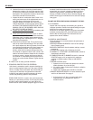
III. Safety check for control system
High limit control test: Set thermostat high enough for boiler
water temperature to reach high limit control setting. When
this temperature is reached, the high limit switch should
o
pen, and the burner should shut off automatically. If the
high limit does not operate to shut off the burner, the high
limit or the wiring is faulty. Repair or replace immediately.
C
ARE AND MAINTENANCE
I. EXTENDED SHUTDOWN, CLEANING OR REMOVAL OF
BOILER FROM SERVICE.
DANGER: Use CAUTION when handling chemicals and
d
r
a
ining hot w
a
ter from a boiler
. S
calding w
a
ter and/or
c
hemicals can cause per
manent injury to the skin, eyes
and respiratory system.
A.Shut down burner by disconnecting all electrical power to
the burner by turning OFF the BURNER EMERGENCY
SWITCH of this boiler. After shutting down burner, while
the boiler is still hot (180°F to 200°F), drain water from
the bottom of the boiler until it runs clear.
B.Provide corrosion protection conditioning to the boiler
water in the heating system.There are a number of com-
mercial heating system preparations available from your
distributor. Follow the preparation manufacturer’s instruc-
tions.
C.T
o clean the fireside boiler surfaces, first shut down
burner by disconnecting all electrical power to the burner
by turning OFF the OIL BURNER EMERGENCY
SWITCH of this boiler in order to perform the following
work in (1) through (10) below.
1. Remove the flue pipe from the boiler flue collar and
clean thoroughly.
2. Inspect the entire vent connector back to the chim-
ney and clean if necessary.
3. Inspect the chimney for soot, debris and other unsafe
conditions of the chimney and take the necessary
action.
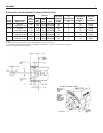
4. Remove the flue collector by first removing the top
jacket panel. The flue collector is held in place by two
hex 1/4-20 screws. Remove the screws and carefully
remove the flue collector.Try not to disturb the flat
fiberglass rope under the flue collector.
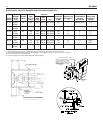
5. When necessary to clean the combustion chamber
you must first CLOSE the suction valve (and return
valve if two pipe). Then disconnect the oil lines from
the burner.The flexible electric conduit connected
from the junction box on the boiler to the burner via a
plastic connector must be disconnected from the
burner by grasping the plastic half of the connector
closest to the flexible conduit and gently pulling it in
the direction of the conduit until it is disconnected.
Remove the single 3/8-16 hex head screw on the
LEFT side of the swinging door.You will need a 9/16”
drive socket. Open the door to completely expose the
combustion chamber for thorough cleaning and for
inspection of target wall, blanket (provided in certain
models;
see rating plate), main cast iron burner door
insulation and burner door fiberglass sealing rope. If
combustion chamber parts above are badly deterio-
rated then replace with or
iginal factory parts avail-
able at your distributor.